


TIMBERWOLF
TW 190TDHB
9
OPERATING INSTRUCTIONS
•
CHECK ball head is well greased.
•
WIND jockey wheel assembly anticlockwise until
the tow head is above the height of the ball hitch
on the vehicle.
•
REvERSE vehicle so the ball hitch is directly below
the tow head.
•
ATTACH breakaway cable to a strong point on the
vehicle, not the ball hitch.
•
GRASP handle on tow head and push back catch
with thumb.
•
WIND jockey wheel assembly clockwise, to lower
the tow head onto the ball hitch.
•
RELEASE handle and continue to wind jockey
wheel clockwise. The tow head should snap into
place on the ball hitch. If it doesn't, repeat
previous 2 steps.
•
WIND jockey wheel up until fully retracted and the
jockey wheel frame is seated in its notch on the
stem. The chipper weight should be fully on the
vehicle.
•
RELEASE jockey wheel clamp and slide the jockey
wheel assembly fully up.
•
TIGHTEN clamp on jockey wheel assembly.
•
CONNECT electrical plug to socket on rear of
towing vehicle and check operation of all the trailer
and vehicle lights.
•
THE chipper is now properly attached to the vehicle.
SAFE TRANSPORTATION
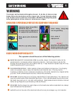
WARNING
DO NOT RIDE ON THE
CHIPPER WHEN IT IS
BEING TOWED.
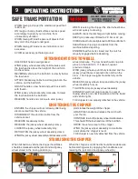
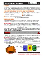
HITCHING ONTO THE TOW BALL
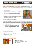
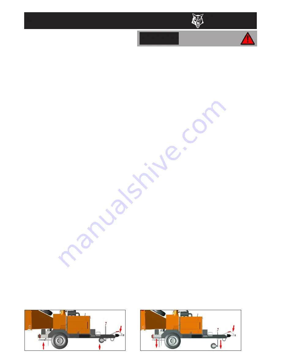
UNHITCHING THE CHIPPER
When the chipper is unhitched it should be made secure
before starting work by applying the handbrake and
lowering the jack stand and jockey wheel (b).
When hitched to a vehicle the chipper handbrake
should be released and the jack stand and jockey
wheel stored in the towing position (a).
•
ENSURE the chipper will not roll away after being
disconnected from the vehicle.
•
DISCONNECT the electrical cable from the
vehicle socket.
•
RELEASE breakaway cable.
•
RELEASE the jockey wheel assembly clamp.
•
LOWER the jockey wheel assembly fully.
•
RETIGHTEN the jockey wheel assembly clamp.
•
WIND the jockey wheel assembly anticlockwise until it
starts to take the weight of the chipper.
•
GRASP the handle and release the catch with
your thumb.
•
CONTINUE to wind the jockey wheel anticlockwise.
This should lift the tow head clear of the ball hitch.
•
DRIvE the vehicle clear of the chipper.
•
WIND the jockey wheel assembly to a suitable
point where the chipper is level.
•
THE chipper is now fully detached from the vehicle.
•
WHEN towing a chipper the maximum speed limit
is 60 mph.
•
ON rough or bumpy road surfaces reduce speed
accordingly to protect your machine from
unnecessary vibration.
•
WHEN towing off road be aware of objects that
may catch the chipper undergear.
•
WHEN towing off road ensure inclination is not
excessive.
•
AvOID excessively pot holed ground.
•
WHEN reversing the chipper the short wheel base
will react quickly to steering.
•
ALWAYS check the discharge is tight before moving.
•
KEEP tyre pressures inflated to 2.9 bar or 42 psi.
•
CHECK wheel nuts are tightened to 90Nm or 65 lbs ft.
•
CLEAR loose chippings and debris from the
machine before departing.
•
ENSURE feed funnel is closed and the catch is
properly engaged before departing.
(a)
(b)
TIMBERWOLF
TW 190TDHB
TIMBERWOLF
TW 190TDHB
STABILISING THE CHIPPER
Содержание TW 190TDHB
Страница 26: ...TIMBERWOLF TW 190TDHB 25 CERTIFICATE OF CONFORMITY...
Страница 27: ...26 EXAMPLE IDENTIFICATION PLATE TIMBERWOLF TW 190TDHB...
Страница 30: ...TIMBERWOLF TW 190TDHB 29 ELECTRICAL PARTS LOCATOR Date Last Modified 19th Sept 05...
Страница 34: ...blank page...