35
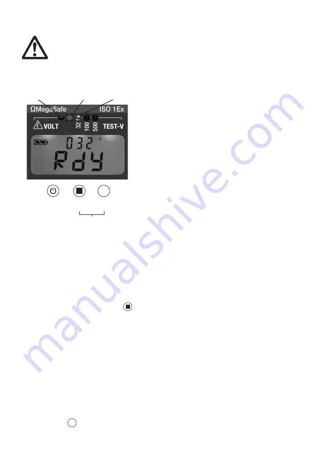
1. Perform the selftest and the zero balance
before each operation. Replace the battery
only outside of Ex areas.
2. Switch-on the device.
3. Establish a secure connection between ISO
1Ex and the test object.
4. External voltage is applied when the red
LED flashes and the display indicates a
voltage >24 V. Then, the pushbutton
is blocked.
Restistance measurements cannot be
performed.
5. „Rdy“ appears in the display when no
external voltage is applied.
6. Start measurements with 32 V test voltage.
If the safety-related limit values of the
plant and the determined external
capacitance allow this the test voltage can
be swiched to 100 / 500 V.
7. Attention! To avoid sparking disconnect
the tester only if the red LED is off and
“Rdy” is indicated in the display.
Rapid discharge is possible with actuation
of pushbutton
32 V
100 V
500 V
.
External voltage
Test LED
Test voltage
On/Off
Selftest
Test
Selection
test voltage
CAL function
32 V
100 V
500 V
Quick user guide 1
This quick user guide serves für
a quick start. In regard of your
own safety, please observe
safety-related Ex characteristic
values and for further informati-
on the detailed user instruction.
Display in the GΩ-Ranges


