background image

Handyscope HS4

User manual

TiePie engineering

Содержание Handyscope HS4

Страница 1: ...Handyscope HS4 User manual TiePie engineering...

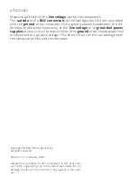
Страница 2: ...t grounded power supplies A short circuit current will ow if the ground of the Handyscope HS4 is connected to a positive voltage This short circuit current can damage both the Handyscope HS4 and the c...

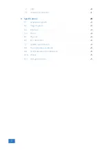
Страница 3: ...s 10 11 4 3 Computers running Windows 8 or older 11 4 3 1 Where to nd the driver setup 11 4 3 2 Executing the installation utility 11 5 Hardware installation 15 5 1 Power the instrument 15 5 1 1 Exter...

Страница 4: ...8 1 Acquisition system 23 8 2 Trigger system 24 8 3 Interface 24 8 4 Power 24 8 5 Physical 24 8 6 I O connectors 24 8 7 System requirements 24 8 8 Environmental conditions 25 8 9 Certi cations and Co...

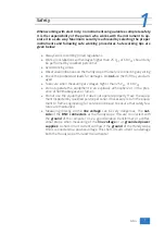
Страница 5: ...g at voltages higher than 25 VAC or 60 VDC Do not operate the equipment in an explosive atmosphere or in the pres ence of ammable gases or fumes Do not use the equipment if it does not operate properl...

Страница 6: ......

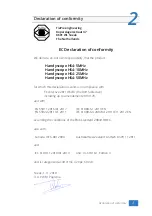
Страница 7: ...in compliance with EC directive 2011 65 EU the RoHS directive including up to amendement 2019 178 and with EN 55011 2016 A1 2017 IEC 61000 6 1 2019 EN EN 55022 2011 C1 2011 IEC 61000 6 3 2007 A1 2011...

Страница 8: ...man health if improperly handled at the Handyscope HS4 s end of life In order to avoid release of such substances into the environment and to reduce the use of natural resources recycle the Handyscope...

Страница 9: ...10 Model 5 12 bit 50 MSa s 25 MSa s 10 MSa s 5 MSa s 14 bit 3 125 MSa s 3 125 MSa s 3 125 MSa s 3 125 MSa s 16 bit 195 kSa s 195 kSa s 195 kSa s 195 kSa s Table 3 1 Maximum sampling rates The Handysco...

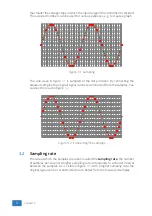
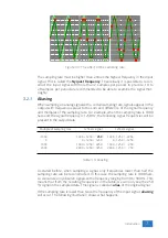
Страница 10: ...es the original signal can be reconstructed from the samples You can see the result in gure 3 2 Figure 3 2 connecting the samples 3 2 Sampling rate The rate at which the samples are taken is called th...

Страница 11: ...uency is 1250 Hz the following signal frequencies will be present in the output data Multiple of sampling rate 1250 Hz signal 1250 Hz signal 1000 1000 1250 250 1000 1250 2250 0 0 1250 1250 0 1250 1250...

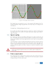
Страница 12: ...aliasing always start measuring at the highest sampling rate and lower the sampling rate if required 3 3 Digitizing When digitizing the samples the voltage at each sample time is converted to a number...

Страница 13: ...the input circuit All signal components available in the input signal will arrive at the input circuit and will be measured In the setting AC a capacitor will be placed between the input connector and...

Страница 14: ...lled the low frequency compensation Each time a probe is used on an other channel or an other oscilloscope the probe must be adjusted Therefore the probe is equiped with a setscrew with which the para...

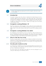
Страница 15: ...nning Windows 8 or older The installation of the USB driver is done in a few steps Firstly the driver has to be pre installed by the driver setup program This makes sure that all required les are loca...

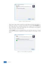
Страница 16: ...andyscope HS4 is disconnected from the computer prior to starting the driver install utility When the Handyscope HS4 is used with an external power supply this must be disconnected too Clicking Instal...

Страница 17: ...Figure 4 3 Driver install Finished Driver installation 13...

Страница 18: ...14 Chapter 4...

Страница 19: ...owered USB hubs do not supply enough cur rent The exact value at which the power is switched o varies per USB controller so it is possible that the Handyscope HS4 functions properly on one computer bu...

Страница 20: ...16 Chapter 5...

Страница 21: ...is connected to the ground of the Handy scope HS4 Connecting the outside of the BNC connector to a potential other than ground will result in a short circuit that may damage the device under test the...

Страница 22: ...18 Chapter 6...

Страница 23: ...shing 3 5 mm positive Figure 7 2 Power connector Besides the external power input it is also possible to power the instrument through the extension connector the 25 pin D sub connector at the rear of...

Страница 24: ...USB port is not available or the computer still can t provide enough power for the instrument an external power adapter can be used When using an external power adapter make sure that the polarity is...

Страница 25: ...rved 6 Ext sampling clock in TTL 19 Reserved 7 Ground 20 Reserved 8 Ext trigger in TTL 21 Reserved 9 Data OK out TTL 22 Ground 10 Ground 23 I2 C SDA 11 Trigger out TTL 24 I2 C SCL 12 Reserved 25 Groun...

Страница 26: ...22 Chapter 7...

Страница 27: ...50 HS4 25 HS4 10 HS4 5 12 bit 50 MSa s 25 MSa s 10 MSa s 5 MSa s 14 bit 3 125 MSa s 3 125 MSa s 3 125 MSa s 3 125 MSa s 16 bit 195 kSa s 195 kSa s 195 kSa s 195 kSa s Maximum streaming rate HS4 50 HS...

Страница 28: ...ension connector Range 0 to 5 V TTL Coupling DC 8 3 Interface Interface USB 2 0 High Speed 480 Mbit s USB 1 1 Full Speed 12 Mbit s and USB 3 0 compatible 8 4 Power Input from USB or external input Con...

Страница 29: ...1 2010 A1 2019 Yes UL 61010 1 Edition 3 Yes 8 10 Probes Model HP 3060 X1 X10 Bandwidth 6 MHz 60 MHz Rise time 58 ns 5 8 ns Input impedance 1 M oscilloscope impedance 10 M incl 1 M oscilloscope impeda...

Страница 30: ...26 Chapter 8...

Страница 31: ...uggestions and or remarks regarding this manual please contact TiePie engineering Koperslagersstraat 37 8601 WL SNEEK The Netherlands Tel 31 515 415 416 Fax 31 515 418 819 E mail support tiepie nl Sit...

Страница 32: ...TiePie engineering Handyscope HS4 instrument manual revision 2 27 February 2020...

Отзывы: