THRUSH AIRCRAFT, INC – MODEL S2R-R1340
AIRCRAFT MAINTENANCE MANUAL
4-10
Effective: 01/01/2008
passages drilled in the case. Oil, from
the tappets, feeds through the push rods
to the rockers, rocker bearings, and valve
clearance adjusting screws.
The surplus oil in the engine proper
drains into the sump, from where it is
pumped back through the scavenge
pump. Oil from the rocker boxes drains
through the push rod covers to the front
case, or through a system of intercylinder
drains to an additional compartment in
the sump where it is returned to the oil
tank. The rear case oil drains through a
tube into the supercharger case, then
into the sump.
PRESSURE RELIEF VALVE
The pressure relief valve provides a
means of adjusting engine oil pressure
so that it will remain within specified
limits during all normal engine operation.
Oil pressure on one side of the valve is
balanced against spring tension on the
other side of the valve. To adjust the
pressure relief valve, proceed as follows:
A. Remove the cap from the main oil
pressure relief valve. Loosen the
adjusting screw locknut.
B. Turn the adjusting screw clockwise
to increase, or counterclockwise to
decrease the oil pressure. Normal
oil pressure is 80 to 100 PSI.
C. After the desired adjustment has
been obtained, tighten the locknut,
reinstall the relief valve cap, and
lockwire.
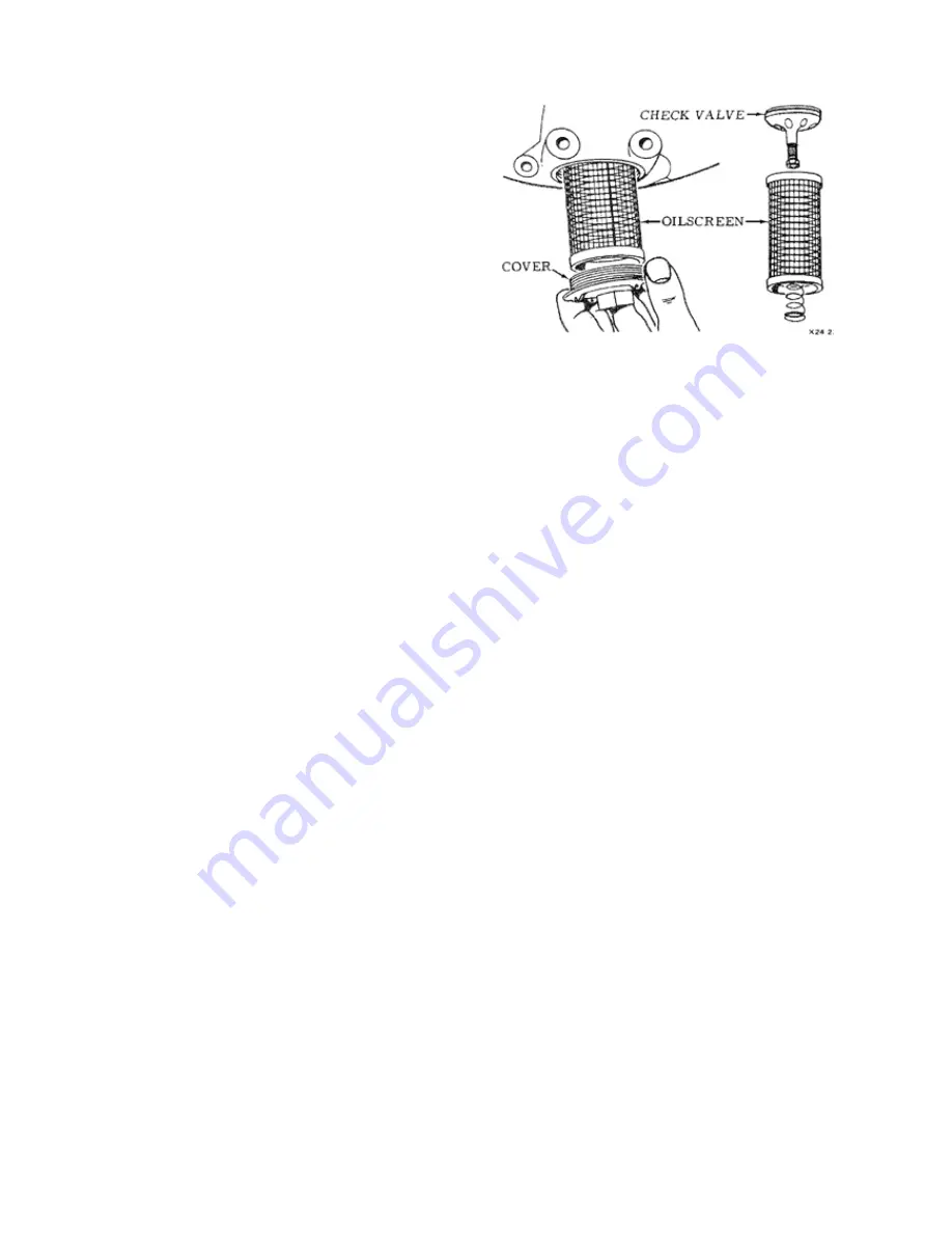
PRESSURE OIL STRAINER
The pressure oil strainer (see Figure 4-3)
is located at the bottom of the rear case.
To remove the strainer, proceed as
follows:
A. Break lockwire and loosen cover nut.
B. Remove cover, spring, oil screen
and check valve assembly.
Figure 4-3: Oil Pressure Screen
Assembly
INSTALLING OIL STRAINER
To install the oil pressure strainer,
proceed as follows:
C. Inspect the screen for distortion or
cracks; check the fit of the screen in
its chamber. Inspect the check valve
to see that it is free and seats
properly.
D. Insert the check valve assembly, oil
seal and oil screen into the chamber.
E. Install the gasket and cover.
Lockwire cover.
PRE-OILING
Pre-oiling is required prior to the initial
start of a new, newly overhauled, or
installed engine depreserved from
storage, to insure proper lubrication for
all bearing surfaces and other moving
parts. To accomplish pre-oiling, proceed
as follows:
A. Install a 50-mesh screen in the pre-
oiling system. Connect the pre-oiling
pump to the oil pressure gage take-
off on the upper left side of the rear
case. Remove the main sump drain
plug.
B. Pump oil into the engine at 45 to 65
PSI at a temperature of 60º to 70ºC
(140º to 160ºF) until approximately
one gallon of oil flows from the main
sump drain plug hole.
Содержание S2R-R1340
Страница 180: ...THRUSH AIRCRAFT INC MODEL S2R R1340 AIRCRAFT MAINTENANCE MANUAL 8 4 Effective 01 01 08 Figure 8 1 Pitot Static System...
Страница 201: ...THRUSH AIRCRAFT INC MODEL S2R R1340 AIRCRAFT MAINTENANCE MANUAL Effective 01 01 08 9 7 Figure 9 5 Agitator and Spreader...
Страница 216: ...THRUSH AICRAFT INC MODEL S2R R1340 AIRCRAFT MAINTENANCE MANUAL 10 14 Effective 01 01 08 Figure 10 2 Stall Warning System...
Страница 220: ...THRUSH AICRAFT INC MODEL S2R R1340 AIRCRAFT MAINTENANCE MANUAL 10 18 Effective 01 01 08 Figure 10 2 Starting System...
Страница 221: ...THRUSH AICRAFT INC MODEL S2R R1340 AIRCRAFT MAINTENANCE MANUAL Effective 01 01 08 10 19 Figure 10 2 Engine Ignition...
Страница 222: ...THRUSH AICRAFT INC MODEL S2R R1340 AIRCRAFT MAINTENANCE MANUAL 10 20 Effective 01 01 08 Figure 10 2 Power Distribution...


