THRUSH AIRCRAFT, INC – MODEL S2R-R1340
AIRCRAFT MAINTENANCE MANUAL
Effective: 01/01/08
2-11
* NOTE *
Since the wing tanks are
interconnected through the
header tank, the fuel can flow
from one tank to another.
Topping off both wing tanks
may be required more than one
time to assure that both wing
tanks are full.
c. After fueling is complete, check for
security of both fill port caps. Wash
any spilled fuel from the wing surface
with clean water.
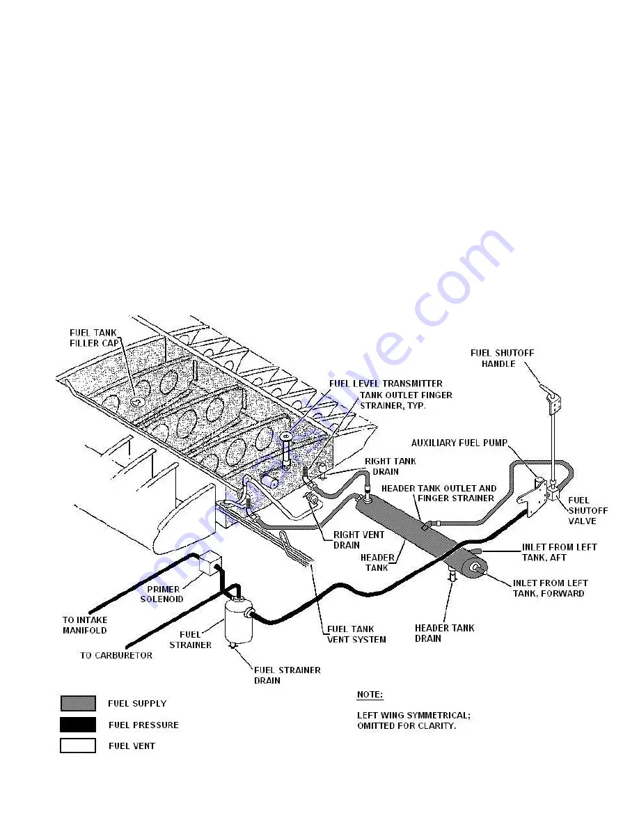
FUEL DRAINS:
(Ref. Fig. 2-2) Four fuel
drain points are provided to allow fuel
draining in order to extract the moisture
sediment and other contamination
entrapped in the system. The drains are
located at the low point of each wing tank
(aft inboard bottom), the bottom of the
header tank, and the bottom of the firewall
fuel filter (Fig. 2-2). Also provided are two
fuel vent drains, located on each side of
fuselage under the wings. All fuel drains
should be drained prior to the first flight of
the day. Drain a small quantity of fuel into
a transparent container to permit
inspection for the presence of moisture,
sediment or othere contaminants. If there
is any indication of contamination, the fuel
should be drained until all evidence of
contamination disappears.
Figure 2-2: FUEL SYSTEM
Содержание S2R-R1340
Страница 180: ...THRUSH AIRCRAFT INC MODEL S2R R1340 AIRCRAFT MAINTENANCE MANUAL 8 4 Effective 01 01 08 Figure 8 1 Pitot Static System...
Страница 201: ...THRUSH AIRCRAFT INC MODEL S2R R1340 AIRCRAFT MAINTENANCE MANUAL Effective 01 01 08 9 7 Figure 9 5 Agitator and Spreader...
Страница 216: ...THRUSH AICRAFT INC MODEL S2R R1340 AIRCRAFT MAINTENANCE MANUAL 10 14 Effective 01 01 08 Figure 10 2 Stall Warning System...
Страница 220: ...THRUSH AICRAFT INC MODEL S2R R1340 AIRCRAFT MAINTENANCE MANUAL 10 18 Effective 01 01 08 Figure 10 2 Starting System...
Страница 221: ...THRUSH AICRAFT INC MODEL S2R R1340 AIRCRAFT MAINTENANCE MANUAL Effective 01 01 08 10 19 Figure 10 2 Engine Ignition...
Страница 222: ...THRUSH AICRAFT INC MODEL S2R R1340 AIRCRAFT MAINTENANCE MANUAL 10 20 Effective 01 01 08 Figure 10 2 Power Distribution...


