


13
Chapter 3 Operation
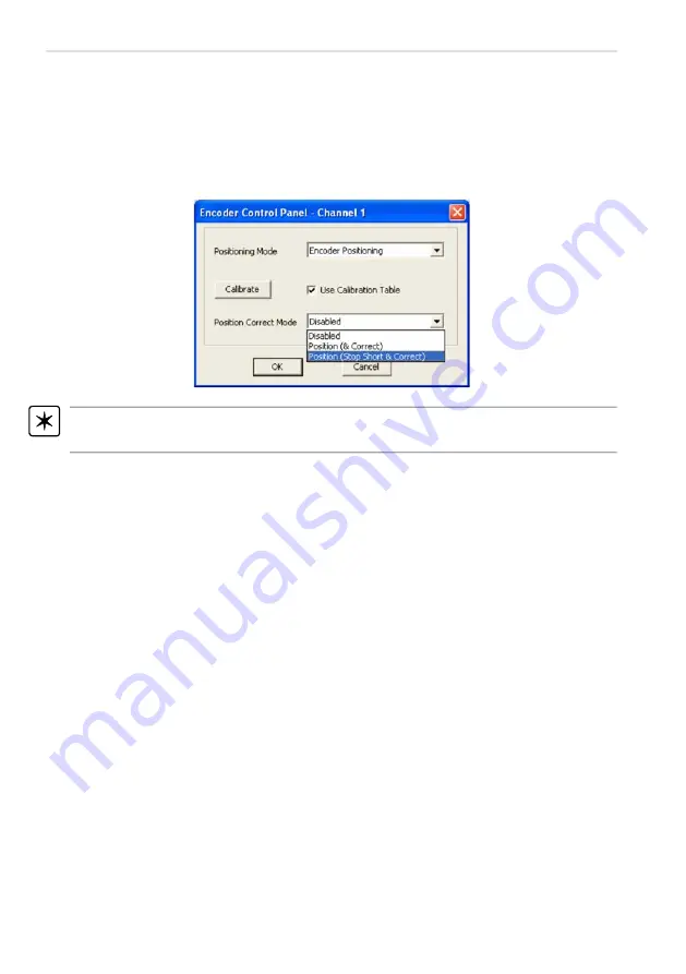
3.4.3 Position Correction Mode
In addition to the calibration table, the APT software can be set to invoke further
positioning correction at the end of an encoded move. This can sometimes be
required when there has been thermal drift in the mechanics since the time the
calibration table was acquired. There are two position correction modes available,
'Position (& Correct)' and 'Position (Stop Short & Correct)' selected using the 'Position
Correct Mode' drop down list.
Note.
For best performance, the backlash correction distance should be set to zero
(either by calling the SetBLashDist method, or via the Settings panel Move/Jogs tab.
Position (& Correct)
In 'Position (& Correct)' mode, the system first attempts to move to the required
encoder based position (with or without calibration table support), and then adjusts
the motor position, using a series of very small correction steps, until the required
encoder position is achieved.
The various correction stepping parameters that affect this operation are found on the
'Encoder' tab of the settings tabbed dialog accessed using the 'Settings' button on the
main graphical panel.
Note that depending on the nature of the lead screw, the stage/actuator may end up
either side of the required position. The correction moves will be applied in both
forward or reverse directions as required in order to achieve the required encoder
position.
In some applications it is desirable to always 'reach' the required final position from
the same direction (conventionally using positive moves on Our stages). To support
this, the second 'Position (Stop Short & Correct)' correction mode is available.
Position (Stop Short & Correct)
When this mode is selected the system stops short of the intended position by a user
specified distance and then issues small position correction steps to achieve the
required final encoder position. Again the user adjustable parameters associated with
this operation are found on the 'Encoder' tab of the settings tabbed dialog accessed
using the 'Settings' button on the main graphical panel.
Содержание MAX200
Страница 1: ...0 Microscopy Accessories Motorized X Y Stages Model Numbers MAX200 MAX201 MAX202 MAX203 ...
Страница 6: ...5 Chapter 2 Overview Fig 2 1 MAX200 stage with 96 hole well plate and mounted on a microscope ...
Страница 31: ...30 MAX200 Series Motorized Microscopy Stages www thorlabs com ...


