


LSK-GG
Chapter 4: Getting Started
Page 6
TTN118193-D02
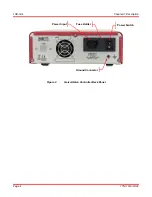
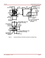
5. Remove the tape on the Input/Output port of the Scan Head.
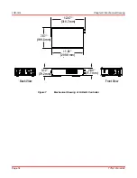
6. Connect one end of the AC power cord to the LSK-GG and the other end to a standard power outlet.
7. Turn on the power switch located on the back panel of the Controller. The mirrors are now centered.
The FAULT LEDs may turn on for few seconds. This is normal as the scanner is ramping up.
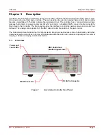
8. Align your light source to the
Input
port (the one with the smaller diameter aperture) of the Scan Head.
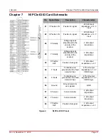
9. To monitor the mirrors’ positions, connect two BNC cables from
X OUT/Y OUT
port to an oscilloscope for
feedback signals. If using a NI 68-pin connector, the pins 30 and 65 provide the output position of X mirror
and Y mirror respectively.
The output is a voltage (±4 V) proportional to the position of the mirror.
Содержание LSK-GG
Страница 1: ...LSK GG Laser Scanning Kit Galvo Galvo Scan Head User Guide...
Страница 22: ...www thorlabs com...