background image

LSK-GG


Chapter 3: Description


Rev A, November 11, 2016 

Page 3 

Chapter 3  Description 


Thorlabs’ Laser Scanning Kit (LSK-GG) helps you to build a customized laser scanning microscopy system. LSK- 

GG consists of a scan head and a controller. The scan head has two precision aligned galvo mirrors and mounting 

features  compatible  with Thorlabs’  optomechanical product  lines.  The  controller  has  a  high  performance  driver 

package that consists of a power supply and driver for each mirror. A shielded DB-25 connector cable connects the 

Scan Head to the Controller. The front panel provides the interface to control the galvo scanners and monitor their 

behavior. The analog control signals from the BNC cables control the position of the galvo mirrors. 

The Galvo/Galvo Scan Head is ideal for high resolution imaging as well as laser scan photoactivation. Add other 

components such as scan lens, tube lens, and photostimulation lasers to build customized optical path for confocal 

imaging, multiphoton imaging, and photoactivation. 

3.1.  Overview 


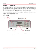
Figure 1 

Galvo/Galvo Controller Front Panel 


BNC Control and 

Monitor Signal Lines 


Power and 

Fault LEDs 

NI 68-Pin Connector 

DB-25 Connector 

Содержание LSK-GG

Страница 1: ...LSK GG Laser Scanning Kit Galvo Galvo Scan Head User Guide...

Страница 2: ...t The software maybe used or copied onlyin accordance with the terms of those agreements No part of this publication maybe reproduced stored in a retrieval system or transmittedin any form or any mean...

Страница 3: ...intaining the LSK GG 7 5 1 Cleaning 7 5 2 Troubleshooting 7 Replacing the Fuse 8 Chapter 6 Specifications 9 6 1 General Specifications 9 6 2 Galvo Mirror Specifications 9 6 3 Fuse Specifications 10 6...

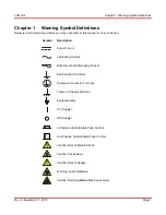
Страница 4: ...ption Direct Current Alternating Current Both Direct and Alternating Current Earth Ground Terminal Protective Conductor Terminal Frame or Chassis Terminal Equipotentiality On Supply Off Supply In Posi...

Страница 5: ...ot specified by Thorlabs the protection provided by the equipment may be impaired CAUTION DO NOT operate in a wet damp or explosive environment WARNING DO NOT put your fingers inside the ports of the...

Страница 6: ...elded DB 25 connector cable connects the Scan Head to the Controller The front panel provides the interface to control the galvo scanners and monitor their behavior The analog control signals from the...

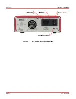
Страница 7: ...LSK GG Chapter 3 Description Page 4 TTN118193 D02 Figure 2 Galvo Galvo Controller Back Panel Ground Connector Fuse Holder Power Input Power Switch...

Страница 8: ...ce laser safe WARNING DO NOT switch on the laser while installing the Laser Scanning Kit This may cause injury due to laser radiation Make sure the laser source is off 1 Place the unit on a dry level...

Страница 9: ...ntered The FAULT LEDs may turn on for few seconds This is normal as the scanner is ramping up 8 Align your light source to the Input port the one with the smaller diameter aperture of the Scan Head 9...

Страница 10: ...x and Scan Head Use a damp lint free cloth to wipe the outer surface of the unit Use Compressed Air to remove the dust particles on the mirrors CAUTION DO NOT touch the surface of the Galvo mirrors wi...

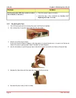
Страница 11: ...power cord from the Controller 2 Use a screwdriver to pop the fuse holder from the Controller 3 Check to see if the fuse is blown If you see a black or brown smudges on the fuse glass or a clearly br...

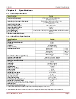
Страница 12: ...ace Quality 60 40 Scratch Dig Average Reflectance 350 450 nm 70 450 550 nm 90 550 650 nm 92 5 650 1080 nm 95 1080 7000 nm 97 Front Surface Flatness 633 nm 4 X Mirror Clear Aperture 6 22 mm x 4 0 mm El...

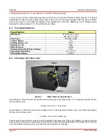
Страница 13: ...nse Time Slow Mounting Type Holder Breaking Capacity Rated Voltage 100 A Operating Temperature 55 125 C DC Cold Resistance 0 043 6 4 Choosing a Scanner Lens Figure 3 Mirror Distance Specification Inpu...

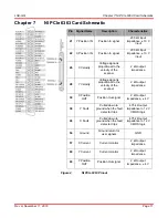
Страница 14: ...2 k output impedance 28 Y Velocity Voltage signal is proportional to the velocity of the scanner 2 k output impedance 30 X Position OUT Position Out signal 2 k output impedance 4 V 38 Y Fault Pulled d...

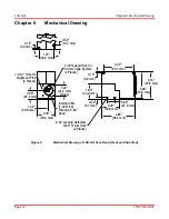
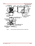
Страница 15: ...Alignment Pins 4 Places 3 35 85 1 mm 3 06 77 8 mm 3 14 79 8 mm 0 15 3 8 mm 0 20 5 1 mm 0 85 21 6 mm 2 00 50 8 mm 3 65 92 7 mm 8 32 Locking Setscrew 5 64 2 mm Hex 2 Places Internal SM1 1 035 40 Threads...

Страница 16: ...1 00 25 4 mm Typical 1 00 25 4 mm 1 06 26 8 mm 1 00 25 4 mm 1 18 30 0 mm Typical 2 08 52 8 mm 3 84 97 5 mm 0 50 12 7 mm Typical 0 49 12 5 mm 0 23 5 8 mm 0 56 14 3 mm 1 70 43 2 mm 3 Places 6 mm Bore f...

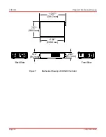
Страница 17: ...LSK GG Chapter 8 Mechanical Drawing Page 14 TTN118193 D02 Figure 7 Mechanical Drawing of LSK GG Controller Front View Back View 3 12 79 2 mm 2 80 71 1 mm 11 81 299 9 mm 7 87 199 8 mm 12 47 316 7 mm...

Страница 18: ...LSK GG Chapter 9 Certifications and Compliance Rev A November 11 2016 Page 15 Chapter 9 Certifications and Compliance...

Страница 19: ...ranty Thorlabs warrants that all products sold will be free from defects in material and workmanship and will conform to the published specifications under normal use when correctly installed and main...

Страница 20: ...abs products such as Pure OEM products that means assemblies to be built into a unit by the user e g OEM laser driver cards Components Mechanics and optics Left over parts of units disassembled by the...

Страница 21: ...da and South America Thorlabs Inc sales thorlabs com techsupport thorlabs com Europe Thorlabs GmbH europe thorlabs com France Thorlabs SAS sales fr thorlabs com Japan Thorlabs Japan Inc sales thorlabs...

Страница 22: ...www thorlabs com...

Отзывы: