Portable Optical Tweezers Kit
Chapter 5: Setup and Adjustment
Page 44
MTN024417-D02
5.2. Controller and Software Setup
5.2.1. LED Controller
Connect the LED to the LEDD1B driver with the cable. Note that the
LED is designed for a current up to
1300 mA
. Set the current limit to
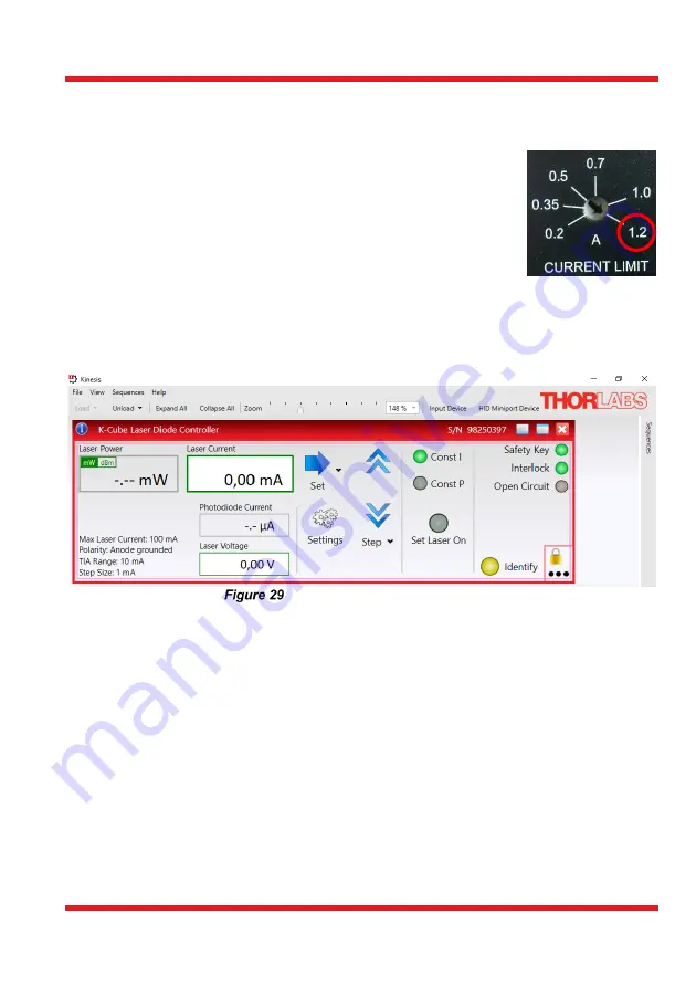
1200 mA on the LED driver by turning the arrow on the current limit
adjuster with a narrow screwdriver (see the photo on the right).
The mode switch on top of the controller should be set to CW.
5.2.2. Laser Controller
Install the Kinesis control software, which will allow for control of the laser diode controller
and sample positioning stages. The software can be installed using the provided CD or
downloaded from the Thorlabs website. Connect the laser controller to the PC only after
you are asked to during the installation. Afterwards, open the newly installed program.
Kinesis Laser Controller Panel
In the Kinesis control panel, see Figure 29, press “Settings”.
•
To operate the laser properly, the polarity setting of the diode will need to be
switched to anode grounded in the “Control” tab. For that, select “Anode” in the
drop-down menu labeled “Polarity”, see Figure 30.
•
Set the maximum current for safe operation of the diode in the tab “Max Current”
to 100 mA, see Figure 30. By activating the “Persist Settings to Hardware”
checkbox, you can store the settings on the device.
•
It is possible to monitor the laser diode with the included photodiode, see Figure
31. This is not necessary for this kit and should not be enabled.
•
Once the polarity and the maximum current are set and persisted to the hardware,
you can operate the laser driver with the controls on the controller itself (rather
than controlling it by software). The current can be set by turning the
potentiometer knob at the top of the controller. For that, the “Advanced” settings
should look like in Figure 31.
Содержание EDU-OT3
Страница 1: ...EDU OT3 EDU OT3 M Portable Optical Tweezers User Guide...
Страница 93: ......
Страница 94: ...www thorlabs com...


