


CM201
Chapter 4: Getting Started
Rev G, January 28, 2022
Page 7
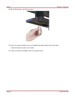
3.
Connect the power cord to a standard power outlet.
E. PMT
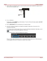
1.
Use the post holder and clamping fork to mount the PMT onto the optical table.
2.
Connect the
USB
port to the computer.
3.
Connect the SMA to BNC cable from the
OUT
port of the PMT to the
AI1
port on the NI Breakout Box.
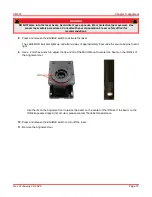
4.
Connect one end of the Armored Fiber Patch cable to the PMT and the other end to the
Pinhole
port of
the CM201.
Содержание CM201
Страница 1: ...CM201 Green Fluorescent Protein Confocal Microscope User Guide ...
Страница 4: ......
Страница 12: ...CM201 Chapter 4 Getting Started Page 8 TTN118795 D02 4 3 Cable Connection Diagram ...
Страница 30: ...CM201 Chapter 8 Mechanical Drawing Page 26 TTN118795 D02 Chapter 8 Mechanical Drawing ...
Страница 33: ...www thorlabs com ...


