Trouble Shooting
MAIN BURNER TROUBLE SHOOTING:
24
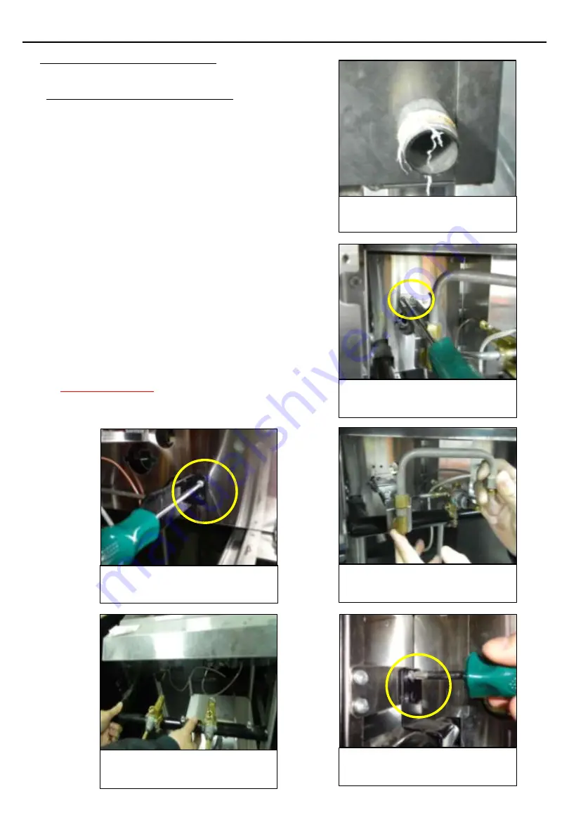
Remove the two mounting
screws on the left side
Remove the two mounting
screws on the right side
Pull out the manifold assembly
and replace if necessary
GAS MANIFOLD ASSEMBLY REMOVAL:
1. Turn-off the pilot.
2. Shut-off the main isolation valve and follow the
lock-out/tag-out procedure.
3. Disconnect the manifold from the gas regulator.
4. Remove the drip tray.
5. Remove the knob and open the control panel
cover, then disconnect the piezo igniter from
the wire.
6. Disconnect the main pipe assy., thermocouple,
and pilot tube assy. from the safety gas valve.
7. Remove the two mounting screws of the left
injector fix plate.
8. Remove the left main pipe assy. and injector fix
plate.
9. Remove the manifold mounting screws (left
side and right side).
10. Pull-out the manifold and replace if necessary.
11. When re-installing the gas regulator, make sure
to put a teflon tape on the thread to prevent
gas leakage.
IMPORTANT NOTE:
Use soap & water to check for
gas leak, after installing all the parts. Do not use
naked flame to check for gas leak.
Remove the two screws of the
left injector fix plate
Take out the injector fix plate
with main pipe assy.
Disconnect the manifold from the
regulator and main gas line
Содержание GH105-N
Страница 5: ...Dimensions GH105 P GH105 N 3 GH106 P GH106 N...
Страница 30: ...Explosion drawing ALL PARTS 28 GH105 P GH105 N...
Страница 33: ...Explosion drawing Spare Parts 31 GH105 P GH105 N...


