THOMSON 42PB120S4 Скачать руководство пользователя страница 20

Connecting other equipment

EN

20

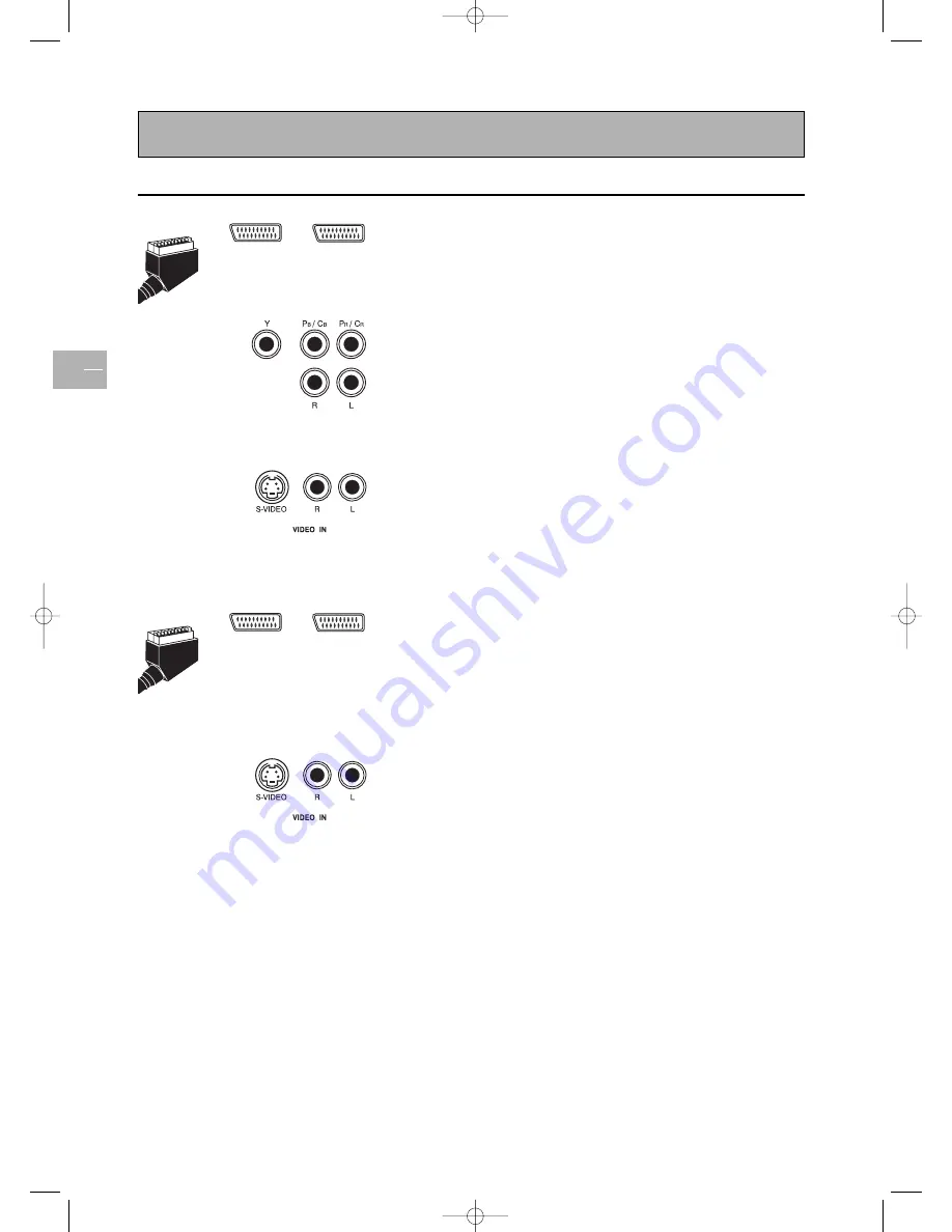
Connecting a DVD player

Using SCART (AV) socket input

1.

Connect the SCART socket on the DVD player to a SCART socket
(AV1 or AV2) on the rear panel of the set.

Using component video input

1.

Connect the green (Y), red (PR/CR), and blue (PB/CB) cinch sockets

on the DVD player to the corresponding cinch sockets on the rear
panel of the set.

2.

Connect the red (R) and white (L) audio cinch sockets on the DVD
player to the R and L audio-in cinch sockets located next to the
PR/CR cinch socket, on the rear panel.

Using S-video input

1.

Connect the S-video socket on the DVD player to the S-VIDEO
socket on the rear panel of the set.

2.

Connect the red (R) and white (L) audio cinch sockets on the DVD
player to the R and L audio-in cinch sockets located next to the 
SVIDEO socket on the rear panel of the set.

Connecting a videorecorder

Using SCART (AV) socket input

This connection gives the best picture and sound quality.

1.

Connect the SCART socket on the videorecorder to a SCART
socket (AV1 or AV2) on the rear panel of the set.

2.

Connect the videorecorder to the antenna wall socket or cable
box.

Using S-video input

1.

Connect the S-video socket on the videorecorder to the .S-VIDEO
socket on the rear panel of the set.

2.

Connect the red (R) and white (L) audio cinch socket on the
videorecorder to the R and L audio-in cinch sockets located next
to the S-VIDEO socket.

3.

Connect the videorecorder to the antenna wall socket or cable
box.

Using TV  input

1.

Connect the antenna out socket on the videorecorder to the
corresponding socket (ANT) on the rear panel of the set.

2.

Connect the videorecorder to the antenna wall socket or cable
box.

AV1

AV2

AV1

AV2

42pb120S4-en  2/07/04  11:32  Page 20

Содержание 42PB120S4

Страница 1: ...13 Volume 13 Displaying status information 13 Accessing TV channels 13 Accessing AV programmes 13 Adjusting the picture 14 In TV mode 14 In PC mode 14 Adjusting the sound 15 Picture in picture PIP 16...

Страница 2: ...r under any circumstances open the set yourself as you risk an electric shock in doing so If you intend to be away for a long period switch the set off at the on off switch located on the rear panel s...

Страница 3: ...creen burns are not covered by the warranty Care and maintenance Always disconnect the TV set from the mains supply before any cleaning operation Clean the screen with a glass cleaning product Never u...

Страница 4: ...erence ACC913 Man uel d util isa tion Be die nu ngsan lei tun g Manuale di util izzaz ione Us er ma nu al Manual de util iza ci n 42PB120S4 Power cord User manual TV set Remote control with batteries...

Страница 5: ...ition the light is off Orange When the TV set is connected to the mains and the main power switch is on the ON position but the power button on the front panel is off the light is orange Green When th...

Страница 6: ...nactive To change programmes within the PIP function To change position of PIP on screen Inactive Inactive red button To access the sleep timer green button Inactive yellow button To access status inf...

Страница 7: ...on On Standby On Standby On Standby On Standby MENU To display the main menu To display the main menu To display the main menu Vertical scrolling Vertical scrolling Vertical scrolling in menus in menu...

Страница 8: ...of the remote control go off Note You can cancel the programming operation at any time by pressing the EXIT button Manual programming This method involves carrying out a manual search for the codes to...

Страница 9: ...s a risk of electric shock Equipment for the UK is supplied with a mains cable fitted with a moulded plug This plug contains safety components and must not be replaced by one sold by general retailers...

Страница 10: ...onfirm Note This is the country you are in or the country whose channels you want to receive if you live near its borders 3 The AUTO INSTALLATION menu appears The Start line is selected Press OK to la...

Страница 11: ...e is to change using the buttons or the numeric buttons Select the Change name option Select the character to be changed using the buttons Scroll through the alphabet using the buttons When you have c...

Страница 12: ...ed standard 3 Once a channel is found if it is recognised its name is automatically detected and displayed on the Name line Note This line is only informative and cannot be selected 4 You can tune the...

Страница 13: ...n on the remote control to display the number and name of the channel you are watching the zoom format the type of sound and the remaining time if the sleep timer is on In PIP mode the PIP display mod...

Страница 14: ...nd select a setting using the buttons Use the V Size option to change the vertical size of the picture Using the buttons move the cursor to the right to enlarge the picture or to the left to reduce it...

Страница 15: ...default To deactivate uncheck the box on the Intern speaker line using the OK button The Audio output option allows you to set the audio output of external speakers When Fixed is selected the Bass Tr...

Страница 16: ...s are added on the upper and lower parts of the screen PAP 16 9 the images are displayed in 16 9 format Black bars are added on the upper and lower parts of the screen Off the function is deactivated...

Страница 17: ...OVERVIEW menu using the MENU button Select the Preferences option and press OK to confirm The corresponding menu appears with the following options Eco mode when this function is enabled In video mod...

Страница 18: ...yet in white when the page has been found A teletext page contains a header line with page and subpage number and broadcaster information date and time channel number etc The navigation bar at the bot...

Страница 19: ...display certain Teletext pages alarm pages To do this display the relevant alarm page and press the buttons to enter subpage mode Enter the time instead of the subpage number e g 1705 for 17 05 and pr...

Страница 20: ...sockets located next to the SVIDEO socket on the rear panel of the set Connecting a videorecorder Using SCART AV socket input This connection gives the best picture and sound quality 1 Connect the SC...

Страница 21: ...the set Using DVI input 1 If your PC is equipped with DVI Digital Visual Interface connect its DVI connector to the DVI IN connector located on the rear panel of the set 2 Connect the audio sockets o...

Страница 22: ...74 85 061 800 x 600 SVGA 85 10 48 364 60 004 1024 x 768 XGA 60 11 56 476 70 069 1024 x 768 XGA 70 12 60 023 75 029 1024 x 768 XGA 75 13 68 677 84 997 1024 x 768 XGA 85 14 63 981 60 020 1280 x 1024 SXG...

Страница 23: ...connected Picture with no sound 1 The signal cable is not connected properly 2 Volume is turned all the way down 3 The sound is muted 1 Make sure that both video and sound inputs are correctly connec...

Страница 24: ...42 inches Aspect ratio 16 9 wide Resolution 852 x 480 Power source Input voltage 100 240 V ac 50 60 Hz Power consumption 240 W average Standby power save 4 W Dimensions W x H x D 1200 x 648 x 22 Net w...

Страница 25: ...CC 913 is available Contact your local retailer for more information A B C D E F Left module Right module Horizontal supports Screws for assembling wall mount 8 Screws for installing onto wooden wall...

Страница 26: ...ket onto the wall Note This package includes two different sets of screws one for mounting on a cement wall and one for a wooden wall Please consult with a qualified installer to make sure that this w...

Страница 27: ...t Note This wall mount is an optional accessory please contact your retailer for more information This type of equipment is to be installed by qualified installers please contact with authorized deale...

Отзывы: