OPERATING INSTRUCTIONS
LIFTING POINTS, SCREW TYPE
THIELE GmbH & Co. KG
# Change indicator
www.thiele.de | [email protected]
B07905-M
replaces B07905-L
© All rights reserved
EN 07.2021
5 | 6
6.3
Influence of Temperature
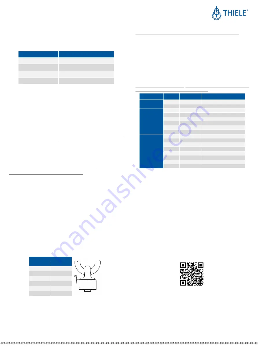
The permissible Working Load Limit of the lifting points reduces at elevated
temperatures.
The reduced Working Load Limit figures shown in the following tables shall only apply
for short-term use at the temperatures indicated.
Temperatu re range
1) #
Remaining Workin g Load Limit (WLL)
-
20 °C ≤ t ≤ 100 °C
100 %
100 °C < t ≤ 200 °C
85 %
200 °C < t ≤ 250 °C
80 %
250 °C < t
≤ 300 °C
75 %
1)
other temperatu re ranges only after consultatio n with the manufac tu re r
If the lifting points have been exposed to temperatures exceeding the maximum values
specified, they must no longer be used.
TWN 1830 and TWN 1884:
Take care for a loss of lubricant depending on several fitting positions and higher
temperatures. A higher wear may occur.
Shorten the inspection interval for that case.
6.4
Environmental Influence
Lifting points must not be used in environments where acids, aggressive or corrosive
chemicals or their fumes are present.
Hot-dip galvanizing or a galvanic treatment is prohibited as well.
7
INSPECTIONS, MAINTENANCE AND DISPOSAL
7.1
General
Inspections and maintenance must be arranged for by the owner!
Inspection deadlines shall be determined by the owner!
Inspections must be carried out and documented by competent persons regularly but
at least once a year, or more frequently if the lifting points are in heavy-duty service.
After three years at the latest they must additionally be examined for cracks. A load
test shall never be considered a substitute for this examination.
The results of the inspection shall be entered into a register (DGUV I 209-062 or DGUV
I 209-063) to be prepared when the lifting point is firstly used. The register will show
characteristic data of the lifting points and other components as well as identity details.
Immediately stop using lifting points that show the following defects:
•
missing or illegible identification/marking,
•
deformation, elongation or fractures,
•
cuts, notches, cracks, incipient cracks, pinching,
•
no freely rotating or turning possible,
•
heating beyond permissible limits,
•
severe corrosion,
•
wear exceeding 10 %, for example in the suspension link diameter area,
•
defect screws,
•
TWN 1830: gap size
„s“
exceeds figures in table below:
Max. gap size „s“ for TWN 1830
Thread
s [mm]
M10
–
M20
1.5
M24
2.0
M30
2.5
M36
3.0
M42
–
M64
3.5
M72
–
M100
4,0
Inspection Service
THIELE offers inspection, maintenance and repair services for lifting points performed
by trained and competent personnel.
7.2
Maintenance
Maintenance and repair work must only be performed by competent persons .
Minor notches and cracks at suspension links may be eliminated by careful grinding
observing the maximum cross section reduction requirement of 10 % and avoid making
more severe cuts or scores.
All maintenance and repair activities are to be documented.
7.3
Disposal
All components and accessories of steel taken out of service are to be scrapped in line
with local regulations and provisions.
8
SPARE PARTS
Only use original THIELE-spare parts. Exclusively use original THIELE screws and bolts
because these are made to meet special requirements.
Type
WLL
Article No.
Screw data
TWN 0127
3,15
Z07742
M20 x 50 ISO 4017 10.9
5,3
Z09017
M24 x 50 ISO 4017 10.9
TWN 1884
0,5
Z11727
DIN 7991 M8 x 30 10.9
0,75
Z11728
DIN 7991 M10 x 30 10.9
1,0
Z11363
DIN 7991 M12 x 35 12.9
1,7
Z10869
DIN 7991 M16 x 50 10.9
2,6
Z11200
DIN 7991 M20 x 60 10.9
3,5
Z11199
DIN 7991 M24 x 70 10.9
TWN 1890
0,63
Z10836
M10 x 45 ISO 4017 12.9
1,0
Z10795
M12 x 50 ISO 4017 12.9
1,7
Z09544
M16 x 70 ISO 4017 10.9
2,5
Z08692
M20 x 80 ISO 4017 10.9
4,0
Z09809
M24 x 90 ISO 4017 12.9
6,0
Z07810
M30 x 100 ISO 4017 12.9
8,0
Z07828
M36 x 120 ISO 4017 12.9
10
Z10136
M42 x 140 ISO 4017 10.9
9
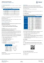
USE OF DIFFERENT SCREWS
If local circumstances dictate that different screws must be used from those supplied
with the installation, or listed in Section 8, the operator must ensure that
•
these fasteners conform to the specified diameter and strength class ,
•
they can achieve the minimum required screw-in depth,
•
they are 100 % crack tested,
•
each bolt has a proven notched impact energy of min. 36 J as a mean value of
three samples tested at -20 °C or at the lowest fitting temperature, if this is below
-20 °C, and that none of the samples fall below 25 J,
•
written confirmation of the crack test and impact energy results is e nclosed with
the technical documentation.
10
STORAGE
Lifting points have to be stored in dry locations at temperatures ranging between 0 °C
and +40 °C.
11
THIELE OPERATING AND MOUNTING INSTRUCTIONS
Current operating and installation instructions are available as a PDF download on the
homepage.
12
PUBLISHING INFORMATION
THIELE GmbH & Co. KG, Werkstraße 3, 58640 Iserlohn, Germany
Tel.: +49(0)2371/947-0
Email: [email protected]


