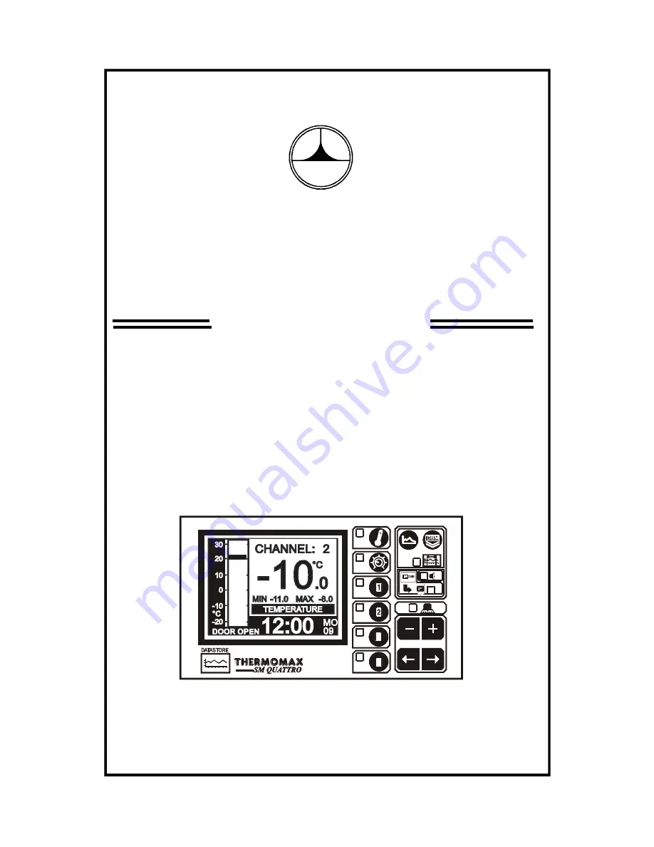
THERMOMAX
SM QUATTRO
4 - CHANNEL DATALOGGER AND ALARM
ENGLISH
3
4
www.Thermomax-Group.com
Страница 1: ...THERMOMAX SM QUATTRO 4 CHANNEL DATALOGGER AND ALARM ENGLISH THERMOMAX 3 4 www Thermomax Group com...
Страница 2: ...Type Selection 14 3 4 SYSTEM DIAGNOSTICS 3 4 1 DATABANK DIAGNOSTICS SCREEN 15 3 4 2 CHANNEL DIAGNOSTICS SCREEN 16 3 4 3 CALIBRATION TRIMMING SCREEN 17 3 5 CHANNEL SCREENS 3 5 1 CHANNEL DISPLAY SCREEN...
Страница 3: ...nd stored to an internal databank Percentage of internal databank used indication in bargraph and digital form Power Supply 220 240V AC Mains Contents of internal databank can be transferred directly...
Страница 4: ...When the unit is connected to the mains supply and the cover is opened the circuits at mains voltage will be exposed Therefore when installing the unit ensure all required connections including batter...
Страница 5: ...n the moulding and slot in the lug over the screw 2 1 3 Level the SM QUATTRO moulding and if using rear entry mark the entry holes in the panel behind the appropriate knock out entries as well as the...
Страница 6: ...low voltage signal cables Connect the supply to the unit as per diagram below using the appropriate input voltage according to the application 2 5 BATTERY The battery supplied is a 9V PP3 nickel meta...
Страница 7: ...alogger Main Screen 1 Channel 1 Display Screen Main Screen 2 Channel 1 Set Screen Channel 2 Display Screen Channel 2 Set Screen Set Screen 1 Set Screen 2 Channel 3 Display Screen Set Screen 3 Channel...
Страница 8: ...lity press and hold the key in order to advance quickly Note The and keys are the only keys which can alter the value of a selected parameter Other keys may be pressed to view or select these paramete...
Страница 9: ...4 display relative humidity in this example 4 This shaded area shows the High Alarm Limits Stage 2 Alarm 5 This shaded area shows the Low Alarm Limits Stage 2 Alarm Note 1 In this example configuratio...
Страница 10: ...creen above 2 Current temperature for channels 1 2 3 Current humidity reading for channels 3 4 4 Maximum and minimum daily temperature humidity readings for each channel Note The display contrast may...
Страница 11: ...utes The indicates that the day on the calendar above is being set The clock is in 24 hour format To advance quickly press and hold the or key for auto repeat 3 Calendar This is the calendar of the mo...
Страница 12: ...lly or by the temperatures dropping within pre set limits the alarm mute will be cancelled automatically 3 Alarm Reset Any current activities delays or counters are reset by pressing the key when the...
Страница 13: ...to connect a door switch for monitoring purposes the status of the door is displayed and logged in graphical form see section 3 6 This option may be enabled or disabled by pressing the or respectively...
Страница 14: ...for 5 seconds respectively When the sensor input is switched ON the unit will operate in normal mode and the actual sensor temperature will be monitored and logged to the databank every 15 minutes If...
Страница 15: ...CTION screen as displayed below This screen gives you the option to choose the sensor type to be used with each of the four input channels This can be either the standard PT100 temperature sensor or t...
Страница 16: ...date on which an alarm condition occurred 6 The TRANSF ON window shows the date on which the contents of the internal databank need to be transferred 7 The MAINS FL window shows the last date on whic...
Страница 17: ...ype used by the SM QUATTRO at present 3 The CALIB DATA window shows calibration values for factory use only and the current temperature reading 4 The LAST CALIB window shows the date when the SM QUATT...
Страница 18: ...on by 2o C Note A known reference temperature should be used THERMOMAX 3 4 To enter the CALIBRATION TRIMMING Screen press and hold the key for 5 seconds THERMOMAX 3 4 Use the keys to move to the chann...
Страница 19: ...p to read humidity will be displayed in this area and all values will be displayed as relative humidity 8 Digital display of Channel temperature humidity with minimum maximum indication The minimum an...
Страница 20: ...alarm If the maximum threshold is exceeded a timer is initiated and no further action is taken at this time 7 High Alarm Stage 1 Delay 1 99 min After the maximum threshold has been exceeded Ref 4 abo...
Страница 21: ...1 Humidity 0 to 99 5 The stage 1 alarm is a time humidity related alarm If the maximum threshold is exceeded a timer is initiated and no further action is taken at this time 8 High Alarm Stage 1 Delay...
Страница 22: ...cted time as shown by the time bar are displayed at the bottom of the screen Ref 4 6 below 4 Plot Time This displays in digital form the time indicated by the time bar 5 Plot Date This shows the date...
Страница 23: ...ins data 3 Current Selection To view the plot of a particular day select the required month from the calendar using the keys followed by the key to accept the selection A second screen appears for the...
Страница 24: ...o 1 This shows the date as selected from the Plot History Function for which the door information below is valid 2 This shows the total door open time in hours and minutes of the selected day 3 This s...
Страница 25: ...he MASTERLINK Software Manual a Plug the 8 way SX plug of the PC Cable Assembly into the SERIAL LINK of the SM QUATTRO b Then plug the 9 way female D type connector into any free serial port in the PC...
Страница 26: ...number of days stored in the internal databank of the Thermomax unit In this example there are 61 days of data stored in the Databank e To increase or decrease the number of days to download press th...
Страница 27: ...HERMOMAX 3 4 PRINT 0001 DAYS INCREASE DECREASE CONFIRM MAX 61 DAYS c The user can now choose any number of days starting from the current day to print directly to the Thermomax serial Printer from 1 d...
Страница 28: ...de Thermomax Serial Printer A6747 Masterlink Hardware Unit C0321 PC Mode 2 This mode is used to network up to 32 units to one PC see illustration below SM QUATTRO PANELMOUNT C0445 SM DUE PANELMOUNT C0...
Страница 29: ...ng screen will appear THERMOMAX 3 4 DATA TRANSFER FUNCTION NOT AVAILABLE PLEASE REFER TO MANUAL In order to download data to the Masterlink Hardware unit or print directly to a Thermomax Serial Printe...
Страница 30: ...network press the key When the key is pressed the SM Quattro will switch off and back on again If you do not wish to disable the network press the key For instructions on how to download data from the...
Страница 31: ...ss the key twice to reveal the following screen THERMOMAX 3 4 Select the window by using the key and press the key to show the following screen THERMOMAX 3 4 With this screen displayed press and hold...
Страница 32: ...tended tighten connections and ensure all couplers are connected correctly Problem Unable to set any of the parameters Keypad will not operate Cause Remedy The Keypad Lock is on See Keypad Lock at the...
Страница 33: ...RO C0428 Sensor 5m Cable A6905 ACCESSORIES Sensor 15m Cable A6915 Sensor Extender 50m A6951 Sensor 25m Cable A6925 MASTERLINK Software C0322 Sensor Extender 10m A6911 MASTERLINK Hardware C0321 Sensor...
Страница 34: ...duct has been tested to the EU EMC 89 336 EEC directive according to the Manufacturers report which is available upon request This product is in conformance with the Low Voltage Directive 73 23 EEC Th...
Страница 35: ...34 SM QUATTRO PANELMOUNT DIMENSIONAL DETAILS...
Страница 36: ...35 WIRINGDIAGRAM Alarm Relay max 5A 220 240 VAC 50Hz Transformer 12V L N E NOTE For SM Quattro applications CH1 CH1 CH2 CH2 CH3 CH3 CH4 CH4...