


MEX VS
Chillers and inverter air / water heat pumps with axial fans
14
7.4.3
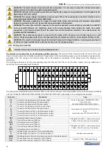
Plant drainage system
When it is necessary to drain the plant, close at first the inlet and outlet manual gate valves (not supplied) and then remove the
pipes that are disposed externally on the water inlet and on the water outlet in order to spill away the liquid contained in the unit
(for easier operation, it is recommended to install externally two draining valves, on the water inlet and on the water outlet,
between the unit and the manual gate valves).
7.4.4
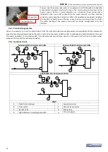
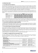
Hydraulic circuit
Models: MEX VS 15 RH and 16 RH
Models: MEX VS 18 RH and 19 RH
A
B
H
F
G
E
D
C
i-HWAK 06/08 V4
A
B
H
F
G
E
D
C
i-HWAK 10/12 V4
SERIE MEX VS 112 RH and 115 RH
A
B
H
F
G
E
D
C
i-HWAK 14/16 V4
KEY
A
Plate heat exchanger
E
Expansion vessel
B
Flow switch
F
Manual air vent valve
C
Service valve
G
Safety valve
D
High efficiency circulating pump with
H
Pressure gauge
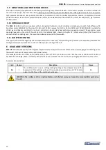
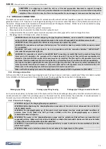
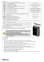
You can use the service valve, when it is necessary to refill the plant or adapt the
concentration of glycol. Unscrew the cap of the service valve and connect to the
hose a pipe of 14 mm or (inner diameter size - check the faucet model that is
installed on your own unit) connected to the water network, and then load the
system by unscrewing the knurled nut. When the operation is concluded, retighten
the knurled nut and screw on the cap. In any case, we recommend you to use for
the water loading of the plant an external tap whose arrangement is by the
installer.
Cap with gasket
Knurled nut
Содержание MEX VS 112 RH
Страница 39: ......


