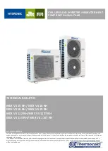
Thermocold MEX VS 112 RH Скачать руководство пользователя страница 12

MEX VS 


Chillers and inverter air / water heat pumps with axial fans


12


7


INSTALLATION 


WARNING:  All  the  operation  described  in  next  chapters  MUST  BE  DONE  BY  TRAINED  PEOPLE  ONLY.  Before  any 
operation  on  the  unit,  be  sure  that  the  electric  supply  is  disconnected.  Be  sure  also,  using  suitable  obstructions, 
that can avoid accidental power supply switching ON until the end of all operations. 

7.1


GENERALITY 

When  installing  or  servicing  the  unit,  it  is  necessary  to  strictly  follow  the  rules  listed  in  this  manual,  to  conform  to  all  the 
specifications of the labels on the unit, and to take any possible precautions. Not observing the rules reported on this manual can 
create dangerous situations. 


After receiving the unit, immediately check its integrity. The unit left the factory in perfect condition; any eventual 
damage has to be questioned to the carrier and recorded on the Delivery Note before signing it. 

The company has to be informed, within 8 days, of the extent of the damage. The Customer should prepare a written statement of 
any severe damage. 


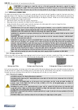
WARNING: The units are designed for outdoor installation. The place of installation must be  entirely far away from 
fire risk. All the necessary measures should be adopted in order to prevent the fire risk in the place of installation. The 
outdoor ambient temperature shall not exceed 46°C. Above this value, the unit is no longer covered by the directives 
in force in the area of pressure equipment. 


WARNING: The unit should be installed so that adequate clearance is available for maintenance and repairation. The 
warranty does not cover costs related to platforms or handling equipment necessary for any maintenance. 


All maintenance and testing operations should be carried out only by QUALIFIED PERSONNEL. 


Before any operation on the unit, make sure the power supply is disconnected. 


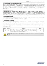
WARNING: MOVING PARTS, RISK OF DEATH. 
Disconnect the power supply and ensure that the fan is stopped before opening the front panel. 


The temperatures of heads and discharge piping of the compressor are usually high. 


Be careful when working near condensing coils. 
The aluminum fins are very sharp and can cause serious injuries. 


After the maintenance operations, close the panels tightly with the fastening screws. 

7.2


LIFTING AND HANDLING 

When unloading and installing the unit, it is highly recommended to 
avoid  any  sudden  move  in  order  to  protect  the  inner  components. 
Units can be lifted by means of a forklift or, in alternative, of belts, 
being  sure  not  to  damage  the  lateral  panels  and  the  cover.  It  is 
important to keep the unit horizontal during these operations. 


7.3


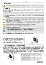
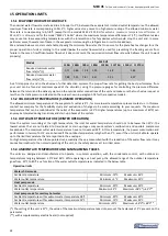
LOCATION AND MINIMUM TECHNICAL CLEARANCES 

The all MEX VS units are designed for outdoor installation: any cover over the unit and location near trees (even if they partially 
cover  the  unit)  has  to  be  avoided  in  order  to  prevent  air  recirculation.  It  is  advisable  to  create  a  proper  basement,  with  a  size 
similar to unit foot-print. Unit vibration level is very low: it is advisable however, to fit a rigid rubber band between basement and 
unit  base-frame.  It  is  also  possible  to  install  anti-vibration  supports  (springs  or  rubbers)  to  keep  vibrations  at  a  very  low  level. 
Absolute care has to be taken to ensure adequate air volume to the condenser. Re-circulation of discharge air has to be avoided; 
failure  to  observe  this  point  will  result  in  poor  performance  or  activation  of  safety  controls.  For  these  reasons  it  is  absolutely 
necessary to respect the following clearances: 
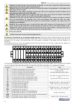
 

MOD. 

MEX VS 15 RH 

1500 

500 

400 

400 

500 

MEX VS 16 RH 

1500 

500 

400 

400 

500 

MEX VS 18 RH 

1500 

500 

400 

400 

500 

MEX VS 19 RH 

1500 

500 

400 

400 

500 

MEX VS 112RH/112T RH  1500 

500 

400 

400 

500 

MEX VS 115RH/115T RH  1500 

500 

400 

400 

500 


Содержание MEX VS 112 RH

Страница 1: ...llation based on the explanations and or on the technical specifications provided in this manual It is besides forbidden the reproduction under any form of the texts and of the figures contained in th...

Страница 2: ...paragraph 2 point f L attrezzatura a pressione rientra nella CAT I L unit quindi esente dall applicazione della normativa PED 2014 68 UE Riferimento Art I paragrafo 2 punto f 2 Harmonized standards a...

Страница 3: ...IMUM TECHNICAL CLEARANCES 12 CAUTION IT IS OBLIGATORY TO INSTALL THE UNIT ON A FIRM AND APPROPRIATE BASEMENT TO SUPPORT ITS WEIGHT CONSIDERING THE WEIGHT OF THE UNIT POSSIBLE VIBRATIONS AND RESULTANT...

Страница 4: ...26 17 1 MODELS MEX VS 15 RH 16 RH 26 17 2 MODELS MEX VS 18 RH 19 RHIN OUT 1 M 26 17 3 MODELS MEX VS 112 RH 112T RH 115 RH 115T RH 27 17 4 INTERNAL PARTS OF THE UNIT 27 17 4 1 Mod MEX VS 15 RH 16 RH 2...

Страница 5: ...e company therefore is not constrained to update the manuals for previous versions of machines It s recommended that the user must follow the instructions contained in this booklet especially those co...

Страница 6: ...the performance of their tasks in safety Operators have to know how to use personal protective devices and have to know the accident prevention guidelines contained in national and international laws...

Страница 7: ...ining the MEX VS units it is required to use the following personal protective equipment Protective clothing Maintenance men and operators have to wear protective clothing that complies with the basic...

Страница 8: ...e 12 h TWA 1000ml m for each of the two components Respiratory protection For rescue and maintenance operation in storage tanks use self contained respirator apparatus The vapors are heavier than air...

Страница 9: ...XCHANGERS The air side exchangers are made up of copper pipes and aluminium fins The tubes are mechanically expanded into the aluminium fins to improve the heat exchange factor The geometry of these c...

Страница 10: ...ds on the size of the unit refer to the technical data shown in chapter 12 safety valve 6 bar that have to be connected with a colleting tank the manual air release valve and the flow switch 5 11 FAN...

Страница 11: ...int of operation for the plant side IMPORTANT NOTE ONLY THE OPTIONAL ACCESSORIES THAT ARE NOT INSTALLED IN THE FACTORY CAN BE REQUIRED AFTER THE ORDER OF THE UNIT WHILE THE FACTORY INSTALLED ACCESSORI...

Страница 12: ...Before any operation on the unit make sure the power supply is disconnected WARNING MOVING PARTS RISK OF DEATH Disconnect the power supply and ensure that the fan is stopped before opening the front p...

Страница 13: ...ator have to be kept clean therefore make sure that are clean after the unit installing the unit and then check them periodically All units are standard supplied with the water flow switch factory ins...

Страница 14: ...H F G E D C i HWAK 10 12 V4 SERIE MEX VS 112 RH and 115 RH A B H F G E D C i HWAK 14 16 V4 KEY A Plate heat exchanger E Expansion vessel B Flow switch F Manual air vent valve C Service valve G Safety...

Страница 15: ...LET TEMPERATURE OUT WATER OUTLET TEMPERATURE CP CAPILLARY 7 7 REFRIGERANT DIAGRAM OF 112RH 115 RH IN OUT DT OS ST LP HP 4WV LR EEV FL FL FL C CLS Pr PV Pr PV CP SE M M P C COMPRESSOR CLS COMPRESSOR LI...

Страница 16: ...controller is positioned To get access to the terminal block please see the indications reported in the paragraph 7 8 2 The wiring to the terminal block has to be realized in accordance to the below...

Страница 17: ...w in the controller s lateral part of the unit 2 Remove the screws connecting the cover plate of the electric box then proceed to connect wire to the terminal block 3 Insert the cables PG cable glands...

Страница 18: ...installed upstream of the system If the temperature drops below 0 C there is serious danger of frost add a mixture of water and glycol in the plant otherwise drain the hydraulic circuits of the plant...

Страница 19: ...s in the atmosphere They have to be collected and delivered to the seller or to proper gathering points at the end of their operating life Refrigerant R410A is mentioned among controlled substances an...

Страница 20: ...rgy Efficiency Index EEI circolatore 0 20 0 20 0 20 0 21 Hydraulic circuit Expansion vessel L 1 1 1 1 Hydraulic connections inch 1 M 1 M 1 M 1 M Minimum volume of water 7 L 31 37 46 51 Noise level Sou...

Страница 21: ...xDxW mm 1060 x 1405 x 455 1060 x 1405 x 455 Max Packing dimensions LxDxW 10 mm 1125 x 1675 x 690 1125 x 1675 x 690 Operating weight kg 119 130 Net Gross weight kg 115 5 126 126 3 137 Prestazioni rifer...

Страница 22: ...teristic curves corresponding to Head pressure Water flow without head losses of the hydronic kit The optimal operating point is shown on each curve under the specified conditions at the apex 3 p 20 T...

Страница 23: ...MEX VS Chillers and inverter air water heat pumps with axial fans 23 MEX VS 18RH MEX VS 19 RH MEX VS 112 RH 112T RH 115 RH 115T RH...

Страница 24: ...act us In this case contact our company for the feasibility study and evaluation of changes to be made according to your requests The maximum temperature that can be maintained at the outlet of the ev...

Страница 25: ...s and inverter air water heat pumps with axial fans 25 Below the operation limits are graphed in the case of air conditioning and sanitary hot water production WATER CHILLER HEAT PUMP MODES DOMESTIC H...

Страница 26: ...orrection factor PDCF Pressure drops correction factor The water flow rate and pressure drop correction factors are to be applied directly to the values given for operation without glycol The water fl...

Страница 27: ...the screw 1 from the side panel for separating the side panel from the front panel Detail A 3 Sequentially twist off the screws number 5 6 7 in order to move shift slightly the front panel and gain a...

Страница 28: ...panel pull the panel forward to remove it in order to loose the hooking tab on the basement indicated as C in the detail B and remove it 17 4 3 Mod MEX VS 112 RH 112T RH 115 RH 115T RH 1 Remove the c...

Страница 29: ...Vac2 FD1 CN13 CN3 PBF1 9 M1 4 11 3 L N P1 TO 02 H 7 TO 02 H 7 42 40 12 L N TB1 25 29 35 77 36 34 26 36 TO 02 M 10 TO 02 J 20 02 C 10 02 D 10 63 62 INVERTER U V W L2 L1 AC L AC N PE INV1 43 43 46 46 L...

Страница 30: ...2 NO2 70 R R 53 0 10 0 10 GND 19 18 17 16 15 14 13 15 14 4 WV1 29 62 63 TO 01 J 18 TO 01 J 18 DO4N DO3 DO5N 80 DO5 DO4 DO3N CEH1 A B 80 R3 A B R1 A B R2 A B 78 78 N2 76 76 67 66 58 N1 57 Auxiliary hea...

Страница 31: ...Trasduttore di bassa pressione Sensore temperatura aspirazione Sonda temperatura acqua in ingresso Descrizione Description Component Componente HP LP OUT ST IN Indice Sonde Probe index Sonda temperatu...

Страница 32: ...E U V W O P P U DRIVE BOARD CON1 CON2 FIN CON3 BN BP2 RUN CM CM CM 0 10V Pin4 Pin5 OP1 12 L2 N2 E CON1 FIN BP1 BN1 L2 N2 12 RY1 U V W E L N Pin 4 Pin 5 INV1 RL1 2 4 6 8 R CHARGE1 114 30 32 34 31 41 15...

Страница 33: ...10 GND 51 52 53 48 49 50 71 100 100 4 WV1 25 113 114 DO4N DO3 DO5N 97 DO5 DO4 DO3N CEH1 A B 97 R3 A B R1 A B R2 A B 102 95 95 N2 93 93 77 N1 76 87 74 75 7 0 1 108 109 90 85 86 77 01 J 7 01 K 7 01 G 1...

Страница 34: ...Component Fusibile 2 x 32A 10 3x38 Fuse 2 x 32A 10 3x38 Indice Fusibili Fuse index Resistenza compressore Compressor heater Compressore Compressor Ventilatore Fan motor Trasformatore Transformer Desc...

Страница 35: ...30 Vac1 TF1 12 Vac1 230 Vac2 12 Vac2 32 46 47 48 40 31 34 44 44 49 49 77 76 73 74 66 FD1 FD2 M1 53 52 112 14 11 12 12 14 39 42 43 43 13 15 60 58 65 75 73 74 L N P1 TO 02 H 7 TO 02 H 7 02 K 8 27 L N TB...

Страница 36: ...10 0 10 70 71 GND 78 76 77 75 73 74 67 65 66 68 68 67 65 66 TO 01 B 4 4 WV1 56 82 83 TO 01 K 21 TO 01 K 21 DO4N DO3 DO5N 100 DO5 DO4 DO3N CEH1 A B 100 R3 A B R1 A B R2 A B 106 98 N2 96 96 116 N1 72 90...

Страница 37: ...onent Componente F1 CB1 TF1 M1 M2 C1 CEH1 Componente Component Controllo bordo macchina Control board Indice Componenti Component index Description Descrizione Trasformatore Transformer Ventilatore Fa...

Страница 38: ...cs see the control manual 21 HANDBOOK FOR SOME CONFIGURATIONS OF INSTALLATIONS For more information about the some configurations you may contact our office and ask for the handbook which collects a s...

Страница 39: ......

Страница 40: ...g Thermocold shall have the right to introduce at any time whatever modifications deemed necessary to the improvement of the product 70026 Modugno Bari Via dei Ciclamini 25 Z I Tel 080 5312623 Interne...

Отзывы: