background image

6

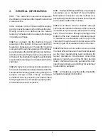
4. Allow the chamber sufficient time to heat up

and observe the temperature on the
thermometer in the vent cap.  The lamp
above the Temperature Control knob should
turn on and off at regular intervals which
indicates the control has stabilized at a
particular set point.

5. If the thermometer indicates that the chamber

temperature is below the desired set point
and the lamp above the Temperature Control
has been turning on and off, rotate the
Temperature Control slightly in a clockwise
direction.  Turn the Temperature Control
slightly counterclockwise if the thermometer
indicates the chamber temperature is above
the desired set point.

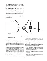
6. Set the safety adjustment:  When the

thermometer indicates the chamber is at the
desired temperature and the lamp above
the temperature control is cycling on and off
at fairly uniform intervals begin to turn the
safety adjustment slowly counterclockwise.
At the moment the safety lamp is illuminated,
the lamp above the temperature control will
turn off.  Rotate clockwise until the lamp
above the safety adjustment is off and the
lamp above the temperature control is back
on. The safety limit has now been set.

7.02

When you are finished using the oven,

simply press the ON/OFF power switch to the
OFF position.  You may leave the temperature
controls in their set positions if you wish to
resume operation at that temperature some
time later.

7.03 Loading

Although the gravity and mechanical convection
ovens rely on different methods of air circulation,
general loading procedures are applicable to
both types and must be followed.  It is important
for uniformity and recovery that air circulation
within the chamber is not restricted.

1. At least one (1) inch (2.5 cm) should be left

between objects placed on the shelves.

NOTE: WITHIN THE MECHANICAL
CONVECTION CABINETS, OBJECTS
SHOULD NOT BE PLACED ON THE
SHELVES IN SUCH A MANNER TO BLOCK
THE MOVEMENT OF HEATED AIR INTO
THE CHAMBER.

2. The bottom floor of the chamber must be

kept free and clear of objects and never
used as a shelf.

3. At no time should solid shelves be substituted

for the shelves that are provided.  Additional
shelves and shelf supports are available
from Precision.

7.04 Safety

1. DO NOT place any explosive, combustible

or flammable materials in this chamber.

2. DO NOT place sealed containers in the

chamber.  Sealed containers, filled with

materials, do not provide room from

expansion or evaporation and can develop

dangerous vapor pressure as the

temperature increases.

3. Avoid placing plastic materials in the oven.

Extreme temperatures may cause plastics

to melt, posing a fire hazard. If plastics are

placed in the oven, do not leave the oven

unattended.

4. Avoid spillage of liquids or powders within

the chamber.  Clean all spills as soon as

possible.  Use caution if oven is still hot.

5. DO NOT evaporate noxious or poisonous

fumes.

6. These ovens are not intended for food

service or the preparation of meals.

7. DO NOT store containers filled with acidic or

caustic solutions within the chambers, as

vapors from these materials will attack the

chamber interior and electrical components,

thus voiding the warranty.

Содержание 14EG

Страница 1: ...s 14EG 6520 6521 25EG 6522 6523 45EG 6524 6525 25EM 6526 6527 45EM 6528 6529 Thermo Electron Corporation Millcreek Road Box 649 Marietta Ohio 45750 USA Phone 740 373 4763 Toll Free 800 848 3080 FAX 740 373 4189 ManualP N3177886 Rev E Dated 11AUG05 ...

Страница 2: ...N CORPORATION MAKES NO REPRESENTATIONS OR WARRANTIES WITH RESPECT TO THIS MANUAL IN NO EVENT SHALL THERMO BE LIABLEFORANYDAMAGES DIRECTORINCIDENTAL ARISINGOUTOFORRELATEDTO THE USE OF THIS MANUAL For repair information or replacement parts assistance from the manufacturer call Technical Services using our toll free telephone number 888 213 1790 FAX 740 373 4189 ...

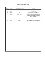
Страница 3: ...ES REVISION STATUS 6 99 B 11 01 6 Add plastics can melt note C 11 02 2 5 7 8 11 High limit cutout for models 25 45 replacedbyhydraulicthermostat ECO 020809A D E 9 04 8 05 12 13 36100121 Correctedsafetythermostatcallout newmanual manufacturelocation ...

Страница 4: ...ING AND DAMAGE 1 3 GENERAL INFORMATION 2 4 SPECIFICATIONS 3 5 INSTALLATION 4 6 EXPLANATION OF CONTROLS 4 7 OPERATION 5 8 MAINTENANCE SERVICING 7 9 PARTS REPLACEMENT 8 10 ELECTRICAL DRAWINGS 11 11 REPLACEMENT PARTS LIST 13 12 WARRANTY 14 ...

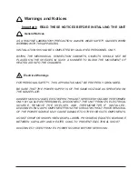
Страница 5: ...AL SAFETY THIS APPARATUS MUST BE PROPERLY GROUNDED BE SURE THAT THE POWER SUPPLY IS OF THE SAME VOLTAGE AS SPECIFIED ON THE NAMEPLATE DANGEROUSVOLTAGESEXISTWITHINTHISUNIT SERVICESHOULDBEPERFORMED ONLY BY QUALIFIED PERSONNEL DISCONNECT THE UNIT FROM ITS ELECTRICAL SOURCE REMOVE THE SHELVES AND THERMOMETER IF INSTALLED DISCONNECTING ANY COMPONENT FROM THE CIRCUIT WITHOUT PRIOR REMOVAL OF THE POWER S...

Страница 6: ...handise was carefully packed and thoroughly inspected beforeleavingourfactory 2 02 Responsibility for safe delivery was assumedbythecarrieruponacceptanceofthe shipment therefore claimsforlossordamage sustained in transit must be made upon the carrier by the recipient as follows 1 VisibleLossorDamage Noteanyexternal evidence of loss or damage on the freight bill or express receipt and have it signe...

Страница 7: ......

Страница 8: ...onvection ovens are ideal fordryingpowders soilsamples papergoods semiconductors and cosmetics 3 03 Models25EMand45EMusemechanical convection as a method of heat transfer Mechanical convection can be defined as a positiveandplanneddirectionalairfloworforced air circulation within the chamber 3 03 1 Air is drawn into the chamber through venttubeslocatedinthebottomoftheovenand is heated as it passes...

Страница 9: ......

Страница 10: ...18 in 390 x 455 mm 21 5 x 24 x 40 in 550 x 610 x 1020 mm Net Weight 69 lbs 31 kg 93 lbs 42 4 kg 103 lbs 46 7 kg 120 lbs 54 4 kg 130 lbs 59 kg Chamber Volume 1 4 cu ft 39 liters 2 5 cu ft 71 5 liters 2 5 cu ft 71 5 liters 4 5 cu ft 129 liters 4 5 cu ft 129 liters Shelves Supplied Maximum 2 6 2 6 2 6 2 10 2 10 Electrical Data all models 50 60 Hz 115V 230V 0 8 kW 7 1 A 0 8 kW 3 5 A 1 3 kW 11 3 A 1 3 ...

Страница 11: ......

Страница 12: ...SE A TWO PRONG ADAPTER PLUG 5 03 Determine the total amount of current beingusedbyotherapparatusconnectedtothe circuit that will be used for this apparatus It is critical that the added current demand see nameplate ofthisandotherequipmentusedon the same circuit does not exceed the rating of the fuse or circuit breaker CAUTION BE SURE THAT THE POWER SUPPLY IS OF THE SAME VOLTAGE AS SPECIFIED ON THE...

Страница 13: ...ecaptoamoreclosedpositiontoretain heat Insert shelf supports into the holes punched in the side walls of the inner chamber Insert the shelvesintotheshelfsupportsandtrytokeepan equal distance between shelves whenever possible Never cover the shelves with foil or reduce their open surface area by more than 75 this will greatly reduce convection and henceuniformityandcontrolwillsuffer A thermometer i...

Страница 14: ...rcirculation general loading procedures are applicable to bothtypesandmustbefollowed Itisimportant for uniformity and recovery that air circulation within the chamber is not restricted 1 At least one 1 inch 2 5 cm should be left between objects placed on the shelves NOTE WITHIN THE MECHANICAL CONVECTION CABINETS OBJECTS SHOULD NOT BE PLACED ON THE SHELVES IN SUCH A MANNER TO BLOCK THE MOVEMENT OF ...

Страница 15: ......

Страница 16: ...operating temperatures The mass of the load can also affect stabilization time 4 Makecertainseverelinevoltagefluctuations arenotoccurring 5 Makecertainallwireconnectionsaresecure attheirterminals 6 Make certain that an intermittent failure of the switch thermostat or wiring has not occurred Isolatethecause repairorreplace 8 03 Heat Loss Inspectdoorgaskettomakecertainitfitsfirmly against cabinet at...

Страница 17: ......

Страница 18: ...op screws which secure it and disconnect motorandheaterterminals 3 Remove screws which secure lower floor and lift out 4 Disconnect remove heater mounting screws remove heater and wires 5 Detach blower wheel from motor shaft 8 04 Heater Resistance Check WARNING DISCONNECT OVEN FROM ITS POWER SOURCE BEFORE PROCEEDING REFER TO THE APPROPRIATE WIRING DIAGRAM AT THE END OF THE MANUAL AND LOCATE THE EL...

Страница 19: ...t screws on each knob 14 EG only 6 Tag lead wires and detach from thermostats 7 Model14EG Removescrewssecuring thermostat to control panel Remove two screws securing angle cover lo cated inside of inner chamber on the front left side This will give you room to pullthermostatbulbsout Model 25 45 Remove thermostat bracketfromcontrolpanel Removether mostatfrombracket Removeknobfrom thermostat 8 Pullt...

Страница 20: ...ecure door handleandreplacehandle 3 Reassemble in reverse order 9 07 Door Latch Grabber on body of unit 1 Disconnectpower 2 Removescrewswhichsecuredoorlatch grabber and remove them from front NOTE Usedretainingnutswillfall intoovenbody 3 Insert replacement latch assembly throughopenslotandfastenwithscrews and washers provided ...

Страница 21: ...TCH CONNECTIONS WIRING DIAGRAM MODEL 14 EG LI 1 N 2 3 LI 2 N 3 HIGH SAFETY TN TN TN THERMOSTAT CONTROL TEMPERATURE SAFETY BK GR WH YL RD BK WH OR L1 N BK RD 3 2 1 LINE CORD ASS Y 3 HEAT SWITCH LEAD ASSY LIGHT ASSY 2 PLACES LEAD ASSY THERMOSTAT 2 PLACES HEATER LEAD ASSY 3 PLACES ...

Страница 22: ... V HEATER 318K OHMS 0 C 6 6K OHMS 100 C 1600 1100 HEATER 32 5 47 HEATER COLD RESISTANCE BETWEEN TB1 4 AND TB1 2 34247440 34247439 PART NO WATTS TB1 2 TB1 2 TB1 1 TB1 1 TB1 4 TB1 3 TB1 2 TB1 1 EMR CHASSIS GROUND GREEN 230 V SAFETY CUTOUT LAMP TEMP CONTROL LAMP EMR 1 WHITE BLACK 2 1 5 4 SAFETY THERMOSTAT OHMS ...

Страница 23: ... 3 T A T S O M R E H T Y T E F A S 4 3 2 5 7 1 3 D E T H G I L N O N T S P D H C T I W S A N 8 1 3 5 7 1 3 T A E H 3 H C T I W S 9 6 2 5 7 1 3 A N 8 1 6 1 5 T O O F G N I L E V E L 6 3 3 5 7 1 3 R E L L O R T N O C E R U T A R E P M E T 4 3 2 5 7 1 3 0 3 7 6 7 1 3 R O S N E S E R U T A R E P M E T A N 5 3 7 6 7 1 3 S S E N R A H N E V O Y M O N O C E A N 7 2 7 6 7 1 3 N O I T I S O P 6 K C O L B M...

Страница 24: ...l warranty period The Technical Services Department must give prior approval for return of any components or equipment At Thermo s option all non conforming parts must be returned to Thermo Electron Corporation postage paid and replacement parts are shipped FOB destination THIS WARRANTY IS EXCLUSIVE AND IN LIEU OF ALL OTHER WARRANTIES WHETHER WRITTEN ORAL OR IMPLIED NO WARRANTIES OF MERCHANTABILIT...

Страница 25: ......

Отзывы: