Regulatory and Safety Information
Thermo Fisher Scientific
Antaris II and Antaris MX Site and Safety Information
27
Страница 1: ...Antaris II and Antaris MX Site and Safety Information ...
Страница 2: ...are ultimately responsible for validation of their systems 2006 2008 Thermo Fisher Scientific Inc All rights reserved No part of this publication may be stored in a retrieval system transmitted or reproduced in any way including but not limited to photocopy photograph magnetic or other record without our prior written permission For Technical Support please contact Thermo Fisher Scientific 5225 Ve...
Страница 3: ...nfectious agents 9 Fire safety and burn hazards 10 Protective housing 11 Cleaning the instrument 11 Lifting or moving the instrument 12 Electrical safety 13 Electrical service 14 Power supplies 14 Power cords 14 Powering on and off 16 Fuses 17 Optical safety 20 Manufacturer s laser information 21 Status indicators 21 Operation panel 23 Corrosives solvents and pressurized gases 24 Pressurized gases...
Страница 4: ...requency immunity 41 Static electricity 41 Ventilation 41 Utility Requirements 43 Electrical requirements 43 Power line conditioning accessories 44 Power consumption 44 Telephone 44 Purge gas 44 Fittings 45 Purge gas generators 47 Pure air dryer 47 Specifications 49 Electrical service specifications 49 Power consumption 50 Purge gas 50 Coolant gas 51 Purge gas generator 51 Pure air dryer 54 Site P...
Страница 5: ... to all applicable safety and regulatory conventions outlined in the General Safety Information section of this manual Location Consult the dimensional drawings of the instrument and accessories when planning the location of your system Leave extra space around the system for clearance and service access Environmental considerations Avoid excessive static electricity extreme temperatures humidity ...
Страница 6: ...elp for information about using a PDF Conventions used in this manual This manual includes safety precautions and other important information presented in the following format Note Notes contain helpful supplementary information Notice Follow instructions labeled Notice to avoid damaging the system hardware or losing data Caution Indicates a potentially hazardous situation which if not avoided may...
Страница 7: ...the instrument remains in its unopened shipping box until the Thermo Fisher Scientific service representative arrives to unpack and install it 24 hours 24 hours 24 hours To prevent damage to the optical components the shipping box must be stored at room temperature for at least 24 hours before the Thermo Fisher Scientific service representative will open it If you did not purchase ValPro and quali...
Страница 8: ...This page intentionally left blank ...
Страница 9: ...ther documentation that came with your instrument If this equipment is used in a manner not specified by Thermo Fisher Scientific the protection provided by the equipment may be impaired In many cases safety information is displayed on the instrument itself The illustrations in this manual show the locations of the safety labels Should any of these labels become loose or unreadable Thermo Fisher S...
Страница 10: ...e EMC requirements Class A equipment US 47CFR15 Radio frequency devices Class A digital device EN61010 1 2001 Safety requirements for electrical equipment for measurement control and laboratory use Part 1 General requirements Installation category II Pollution degree 2 UL61010 1 2004 Safety requirements for electrical equipment for measurement control and laboratory use Part 1 General requirements...
Страница 11: ... Part 1 General requirements Installation category II Pollution degree 2 UL61010 1 2004 Safety requirements for electrical equipment for measurement control and laboratory use Part 1 General requirements Installation category II Pollution degree 2 CAN CSA C22 2 NO 61010 1 2004 Safety requirements for electrical equipment for measurement control and laboratory use Part 1 General requirements Instal...
Страница 12: ...ves and standards FCC Federal Communications Commission The FCC is an independent United States government agency directly responsible to Congress The FCC was established by the Communications Act of 1934 and is charged with regulating interstate and international communications by radio television wire satellite and cable The FCC s jurisdiction covers the 50 U S states the District of Columbia an...
Страница 13: ...entific products which may assist the detection of substances subject to the RoHS Directive are available at www thermo com WEEERoHS Hazardous materials and infectious agents Instruments components accessories and other associated materials may not be returned to Thermo Fisher Scientific or other accessory manufacturers if they are contaminated with radioactive or other hazardous materials infecti...
Страница 14: ...nt or on heated accessories to warn you about hot surfaces in the vicinity of the symbol The following Cautions and Warnings provide additional information about fire safety and preventing burn hazards Caution The near infrared source bulb may be very hot It stays hot for up to 5 minutes after you turn off your instrument To avoid being burned or starting a fire handle the source assembly only by ...
Страница 15: ...otective cover for transport stresses after shipping Cleaning the instrument If the outside of the instrument needs cleaning turn off the power and disconnect the power cord from AC power Then use a damp not wet soft cloth and a mild soap to clean the outside of the instrument Do not use harsh detergents solvents chemicals or abrasives these can damage the finish See the section entitled Powering ...
Страница 16: ...ving an instrument get a second person to help you Avoid electrical and crush hazards Be sure to lift from each side of the instrument not the front and back Notice Always support the instrument baseplate from underneath when lifting or moving these instruments Grasping the power supply on the rear panel of the instrument when lifting will damage the instrument Damage caused by improper lifting is...
Страница 17: ...capacitors may remain charged for up to 30 seconds You may also see one or more symbols on or near switches and connectors on your instrument These symbols are often used to identify connectors or help you to locate user replaceable fuses The table that follows shows the symbols and lists the meaning of each Check the documentation that came with your instrument if you find a symbol that is not in...
Страница 18: ...rning Avoid shock and fire hazards Always use an exact replacement for the fuses bulbs and power supplies Power cords You must be sure to use an appropriate power cord for your specific electrical service The power cord supplied with the analyzer is a 3 wire grounded power cord appropriate for use in the country listed as the shipping destination for the system If the power cord you received is no...
Страница 19: ... 8303 Indian South African old British Plug Style BS 546 Italian Plug Style CEI 23 16 VII Swiss Plug Style SEV 1011 Israeli Plug Style SI 32 Continental Europe or Schuko Plug Style CEE7 7 Argentinean Plug Style IRAM 2073 Chinese Plug Styles GB2099 1 and GB1002 1 North American 220 Volt locking British or United Kingdom Plug Style BS 1363 with a 13 amp fuse Thermo Fisher Scientific Antaris II and A...
Страница 20: ...n Powering on and off Power on the instrument by pressing the power switch on the rear panel I on O off Power switch Antaris II Power switch Antaris MX 16 Antaris II and Antaris MX Site and Safety Information Thermo Fisher Scientific ...
Страница 21: ...protect the power supply from excessive current Use replacement fuses which meet the following specifications Warning Avoid shock hazard and overheating Always use an exact replacement for the fuse Fuse characteristic Specification Current max 2 A Voltage 250 V Size 6 3 mm x 32 mm 0 25 in x 1 25 in Action Fast acting Warning To avoid the risk of electrical shock always turn off the instrument and ...
Страница 22: ... power connector Fuse compartment Fuse Power switch AC power connect c or ompartment Antaris MX Antaris II 2 Remove the fuse holder from the fuse compartment Use a 1 8 in flat blade screwdriver to pry the fuse cover open and then pry the fuse holder out of the fuse compartment Fuse cover Fuse holder 18 Antaris II and Antaris MX Site and Safety Information Thermo Fisher Scientific ...
Страница 23: ...lace it with a new fuse of the correct type and amperage rating If you need to replace the fuses use only 6 3 mm x 32 mm 0 25 in x 1 25 in 2A 250 VAC fast acting fuse 5 Push the fuse holder back into the fuse compartment until it is completely inserted and then close the fuse cover 6 Reconnect the power cord and turn on the power by pressing the power switch on the rear panel of the instrument The...
Страница 24: ...laser head Warning Never stare into the laser beam or at its bright reflection Never tamper with the laser head on the main laser assembly even if you are replacing a defective laser Injuries from exposure to laser light or high voltage may result Caution Do not stare into the sample window of an Integrating Sphere the sampling tip of a fiber optic probe or the fiber optic probe connectors on the ...
Страница 25: ...power 1 6 mW beam diameter 0 65 cm 1 e2 beam divergence 1 5 mrad max spacing C 2L 1039 MHz internal operating voltage 1600 VDC CDRH classification IIIa Status indicators The status indicators show the current status of the instrument Power This indicator lights when the instrument power is on and the power supply voltage is within specifications Scan This indicator flashes with each scan of the in...
Страница 26: ...Regulatory and Safety Information De ssi can t La se r Sc an Po we r So urc e Antaris II Da ta Da ta Antaris MX 22 Antaris II and Antaris MX Site and Safety Information Thermo Fisher Scientific ...
Страница 27: ...tton ejects and retracts the module Da ta Da ta Antaris MX De ssi can t La se r Sc an Po we r So urc e Antaris II A flashing light indicates when the operator needs to pay attention to the system monitor A light on steadily indicates that the operator can initiate the action described on the computer monitor by pushing the green button or choosing the default button on the computer screen Thermo F...
Страница 28: ...ps in place until the cylinder is connected to a regulator or manifold Never lift a cylinder by the cap Always provide a legible label or marking to identify the contents of a cylinder and any precautionary warnings Inspect the cylinders regularly for corrosion valve damage or leaks and evidence of tampering Never use a flame to detect flammable gas leaks Regulate the flow of gas from the gas sour...
Страница 29: ...lammable vapors from collecting in the atmosphere surrounding the instrument Solvents containing halogenated hydrocarbons Chlorinated solvents perfluorochlorinated solvents and other materials containing halogenated hydrocarbons are often used as FT NIR solvents The pyrolysis of these solvents by a near infrared source may produce hydrochloric acid HCl hydrofluoric acid HF or phosgene COCl2 Hydroc...
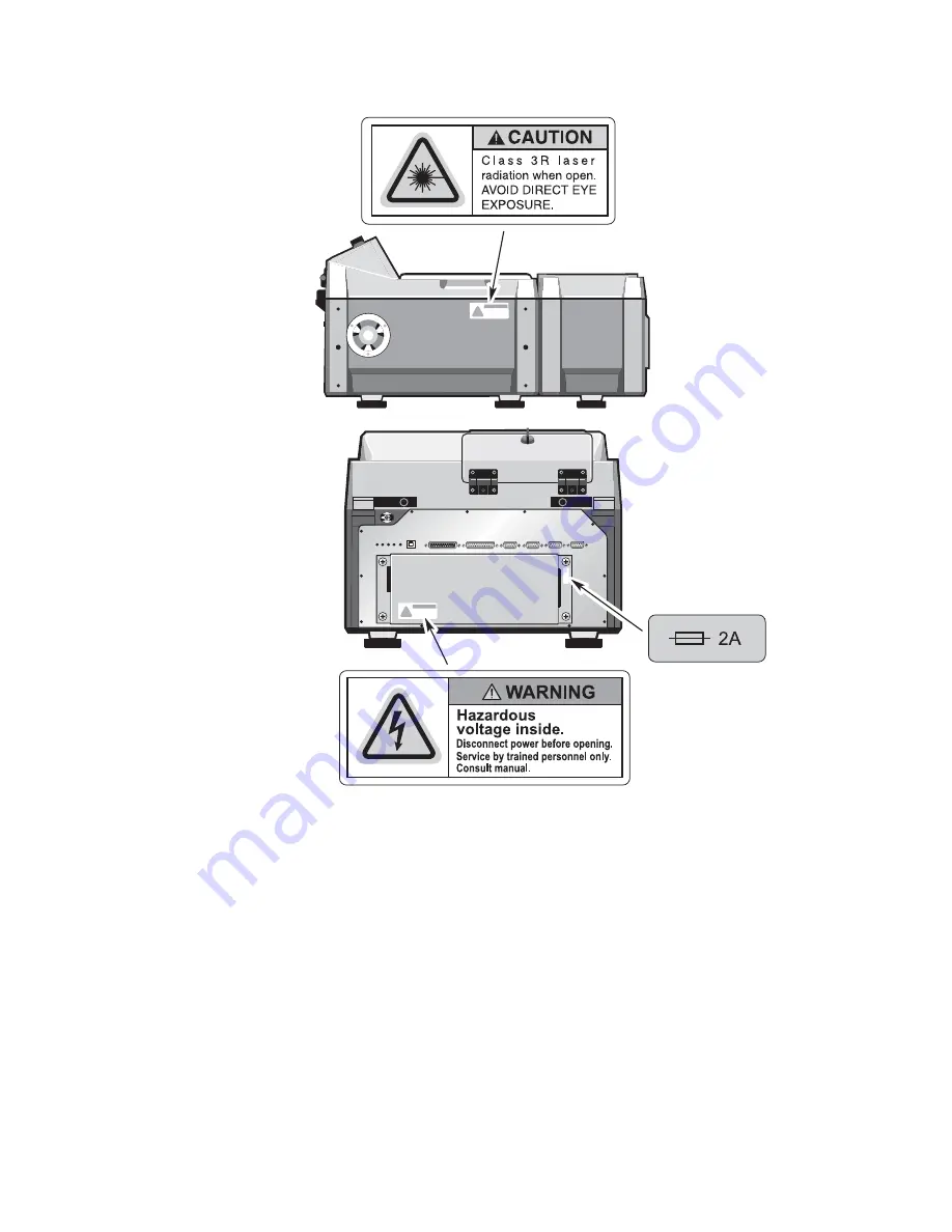
Страница 30: ...he instrument Should any labels come loose or become unreadable Thermo Fisher Scientific will supply new ones The parts list that came with your system contains information about obtaining replacement labels Antaris II De ss ica nt La se r Sc an Po we r So urce 26 Antaris II and Antaris MX Site and Safety Information Thermo Fisher Scientific ...
Страница 31: ...Regulatory and Safety Information Thermo Fisher Scientific Antaris II and Antaris MX Site and Safety Information 27 ...
Страница 32: ...Regulatory and Safety Information Antaris MX 28 Antaris II and Antaris MX Site and Safety Information Thermo Fisher Scientific ...
Страница 33: ...Regulatory and Safety Information Thermo Fisher Scientific Antaris II and Antaris MX Site and Safety Information 29 ...
Страница 34: ...Regulatory and Safety Information Accessories Heated cell 30 Antaris II and Antaris MX Site and Safety Information Thermo Fisher Scientific ...
Страница 35: ...a power cord approximately 2 5 m 8 ft long Be sure the installation surface is rigid within 2 of level and capable of supporting twice the instrument weight While vibration will not damage the instrument excessive vibration may compromise spectral quality and measurements Make sure the system will fit in the work space you choose Compare the work space with the dimensions shown in the next section...
Страница 36: ... that computer with no network access For customers who are obliged by FDA regulations to limit logons to the system the network administration or other designated person may log on personally and remain present while the service representative installs the instrument and or performs maintenance or service functions System dimensions A standard table depth of 76 cm 30 in will accommodate either of...
Страница 37: ...ARISMX Process Analyzer 16 in 9 75 in 24 765 c 20 in m 2 in 2 in 5 08 cm 5 08 cm 19 in 48 26 cm 24 in 60 96 cm 5 in 12 7cm 50 8 cm 40 64 cm Front view Antaris MX without fiber optic cable strain relief or SabIR holsters Top view Antaris MX with fiber optic cable strain relief Thermo Fisher Scientific Antaris II and Antaris MX Site and Safety Information 33 ...
Страница 38: ...le extenders Contact technical support for additional information Both desktop and integrated computers are available Typical computer component dimensions follow Item Height Width Depth Integrated computer includes monitor 38 cm 15 in 30 cm 12 in 5 cm 2 in Desktop computer 48 cm 19 in 21 5 cm 8 5 in 46 cm 18 5 in Monitor 40 cm 15 5 in 56 cm 22 in extended 38 cm 15 in 22 cm 8 5 in Keyboard 6 cm 2 ...
Страница 39: ... 70 cm 27 5 in Des sica nt Las er Sca n Pow er Sou rce 82 5 cm 32 5 in 13 5 cm 5 31 in 54 cm 21 31 in Antaris II with integrated computer Da ta Da ta 70 cm 27 5 in 21 31 in 54 cm 24 in 60 96 cm 13 5 cm 5 31 in Antaris MX with integrated computer 91 cm 35 75 in 76 2 cm 30 0 in 92 cm 36 in 99 cm 39 in Antaris wheeled cart Thermo Fisher Scientific Antaris II and Antaris MX Site and Safety Information...
Страница 40: ...the NIR beam to external samples Optional optical and mechanical parts are required if you plan to use this capability 32 46 cm 12 78 in 11 43 cm 4 50 in Required clearances There must at least 63 5 cm 25 in of clearance above the base of the instrument so that the compartment covers can be fully opened and to allow access to internal parts during servicing For instruments with integrated computer...
Страница 41: ...instrument can pose a rack enclosure tip hazard unless appropriate anti tip extensions feet or anchors are in place Use the information that follows to have them designed by your rack enclosure manufacturer or a qualified structural engineer prior to the installation of the instrument The structural engineer who designs your restraints will need the weight information for the instrument components...
Страница 42: ...ven devices should be installed in a separate enclosure or on a solid level floor near the instrument enclosure Vibrations from the motors compressors and pumps can distort your spectral data Enclosure environment To prevent damage to the instrument you must provide cooling and desiccating devices and maintain ambient temperature and humidity inside the rack enclosure as follows Temperature 15 C a...
Страница 43: ...he instrument near heating or air conditioning ducts or areas where the workspace temperature may exceed recommended limits Keep sources of heat such as hot plates and heating mantles away from the instrument Humidity Excessive exposure to moisture may degrade components inside the enclosure For instruments that are not purged or desiccated humidity must be maintained at 20 to 50 noncondensing For...
Страница 44: ...ginally shipped in Extreme changes in temperature and humidity may cause moisture condensation which can permanently affect the optical components Vibration isolation Extreme floor vibration or acoustical noise from heavy manufacturing equipment or other sources can affect the performance of your instrument Minimize or eliminate excessive noise and vibration wherever possible The rollout drawer in...
Страница 45: ...ic electricity in your facility protect your system especially when you are servicing or handling components inside the instrument by following your company s established guidelines for reducing electrostatic discharges Ventilation There are no special ventilation requirements for an Antaris system The types of analyses you plan may require special ventilation for example if you will be analyzing ...
Страница 46: ...aintain appropriate safety practices Be sure to provide storage space for solvents containing halogenated hydrocarbons that is away from the instrument they should not be left in or on any of the sampling modules for an extended time and the instrument must be purged while the solvents are used An optional purge kit is available from Thermo Fisher Scientific 42 Antaris II and Antaris MX Site and S...
Страница 47: ...ipped with a 3 wire line live neutral and ground If you suspect power quality problems at your site or if your system will be installed in a heavy industrial environment we recommend that a power quality audit be performed before installation Contact Thermo Fisher Scientific or your local electrical authority for more information Danger To assure a good ground connection and avoid shock hazard do ...
Страница 48: ...nstrument Should you require assistance from Thermo Fisher Scientific being able to use the phone while operating the instrument will save time Purge gas Standard instruments are sealed and desiccated to prevent damage to optical components from environmental humidity and corrosive solvents If your instrument environment is excessively humid above 95 non condensing or contaminated by routine use o...
Страница 49: ...f you ordered the purge kit option for your instrument install the purge line and the necessary fittings before the system arrives Shutoff valve Supplied by you Supplied by Thermo Electron Either 1 4 male fitting or 3 8 female fitting 3 8 to 1 4 Male reducing nipple Pressure coupling Install the source line within 10 ft of the proposed location for your instrument The line must be installed vertic...
Страница 50: ... your instrument arrives you will need a 1 4 inch open end wrench to attach the pressure coupling If you used a 3 8 inch female fitting you will need a 11 16 inch open end wrench to tighten a reducing nipple and a 3 4 inch open end wrench to tighten the pressure coupling Always use pipe tape to prevent leaks at the fittings Shutoff valve Pressure regulator Pressure coupling 3 8 to 1 4 male reducin...
Страница 51: ...pressure for proper operation Failure to supply this pressure may allow moisture to enter the system causing permanent damage See the preceding table for the minimum pressure values Pure air dryer Thermo Fisher Scientific also offers a complete dry air generating system for providing instrument purge Since this system contains an air compressor it can be used in facilities that do not have a sourc...
Страница 52: ...at you purge the dryer of water and particulates by running it for at least 12 hours at nominal air flow Otherwise you risk severe damage to the optical components in the instrument when you connect the pure air dryer 48 Antaris II and Antaris MX Site and Safety Information Thermo Fisher Scientific ...
Страница 53: ...te your power source within 3 m 10 ft of the instrument rear panel Item Specification Electrical service 3 wire live neutral earth ground Nominal operating AC input 90 V to 264 V Nominal operating current 1 7 A at 115 V 1 0 A at 230 V Maximum startup AC input current 15 A at 115 V 30 A at 230 V Line frequency 47 Hz to 63 Hz Line disturbances Sags surges or other line disturbances must not exceed 1...
Страница 54: ...rd printer 200 W 683 Btu hr Values shown are estimates See the power specifications on the rear panels or undersides of these units Purge gas Locate the purge source within 10 ft of the instrument Item Specification Source line pressure 20 psig min 1 4 atm min 150 psig max 10 2 atm max Purge pressure 10 psig min 0 7 atm min 20 psig max 1 4 atm max Flow rate 15 scfh min 7 1 l m min 20 scfh max 9 4 ...
Страница 55: ...n 7 1 l m min 20 scfh max 9 4 l m max Filtering 10 micron filter removes particulate matter and oil Dew point 70 C 94 F or below for best performance Purge gas generator The following illustrations show the dimensions of the purge gas generators and the locations of holes that can be used for mounting the generators on a wall Models 75 45 and 75 45EU fit easily on top of a bench or table When not ...
Страница 56: ...ng hole 4 33 4 cm 13 2 in 33 8 cm 13 3 in Model 75 45 and 75 45EU 23 cm 9 in 69 7 cm 27 4 in Front Right Side 23 5 cm 9 2 in 32 4 cm 12 8 in Mounting hole inside 2 Model 75 52 and 75 52EU 52 Antaris II and Antaris MX Site and Safety Information Thermo Fisher Scientific ...
Страница 57: ...egeneration 14 l m 30 scfh 14 l m 30 scfh 28 l m 60 scfh 28 l m 60 scfh minimum inlet air pressure 4 08 atm 60 psig 4 08 atm 60 psig 4 08 atm 60 psig 4 08 atm 60 psig CO2 concentration 1 ppm 1 ppm 1 ppm 1 ppm maximum inlet air temp 25 C 78 F 25 C 78 F 25 C 78 F 25 C 78 F inlet outlet port size 1 4 in NPT female 1 4 in NPT female 1 4 in NPT female 1 4 in NPT female shipping weight 11 kg 25 lb 11 kg...
Страница 58: ...69 065600 nom input line voltage freq 110 VAC 60 Hz 220 VAC 50 Hz dew point 73 C 100 F 73 C 100 F max air flow rate at 80 psig 28 l min 60 scfh 28 l min 60 scfh CO2 concentration 1 ppm 1 ppm outlet port size 1 4 in NPT female 1 4 in NPT female shipping weight 114 kg 250 lb 114 kg 250 lb 54 Antaris II and Antaris MX Site and Safety Information Thermo Fisher Scientific ...
Страница 59: ...ed to be present during the installation to complete the following tasks Set up users in the Windows operating system Set up Windows security features Change settings for the RESULT Operation audit log if necessary Set up another RESULT administrator account if necessary Note A system administrator must be present during installation of an Antaris system The Thermo Fisher Scientific service engine...
Страница 60: ...There is adequate clearance around and above the system Utility service A dedicated power line is available There is sufficient power to run the instrument and all accessories There is a definite earth ground not neutral for power outlets Adherence to local building and safety codes is verified A source of dry air or nitrogen is installed if you plan to purge the instrument Computer requirements C...