24
E.
Symptom: Blower cycles on and off after the burner has shutdown.
Item to check:
1) Increase the fan off time by changing the DIP switch selections on SW2.
Refer to Table 2 for blower delay off settings.
NOTICE: If the high limit control is faulty, it should be replaced. However, it must
only be replaced by the same make and model as the original. Refer to the
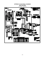
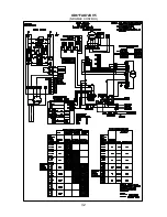
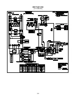
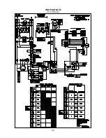
electrical diagrams for proper electrical connections.
Flame Sensor (“Cad Cell”) Checkout Procedure
Refer to the oil burner manufacturer’s operating instructions (included with the furnace)
for detailed cad cell troubleshooting.
Replacement Parts
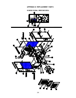
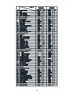
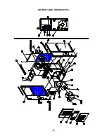
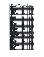
Appendix D of this manual contains a list of replacement parts available for these
furnaces.
MAINTENANCE
Air Filter(s)
c
CAUTION:
To avoid injury from moving parts, hot surfaces, or electrical shock,
shut off the power to the furnace and allow the furnace to cool BEFORE removing
any furnace access doors to service air filters.
These furnace models are factory-supplied with a permanent-type, air filter. At least twice
a year, remove the air filter(s) for cleaning. Clean a filter by soaking it in water with a mild
detergent and then rinsing it with clean water. Allow the filter to air dry before reinstalling
it in the furnace filter rack.
If the furnace, or duct system, is equipped with disposable-type (paper element), air
filters, inspect them every month for an excessive accumulation of dust and dirt. Replace
disposable air filters at least twice a year. Make certain the replacement filter is the same
size as the one being replaced. The filter size is marked on the outer edge of the air filter.
Install the filter with the arrow marked on the filter pointing toward the furnace.
Oil Burner
NOTICE: A qualified heating contractor MUST service the oil burner in this furnace
at least once a year.
Generally, service to the burner will involve a thorough inspection and cleaning of the
burner, replacement of the oil nozzle and oil filter, and readjustment of the burner to
achieve proper ignition and clean combustion.
Содержание OD6FA072D48
Страница 32: ...31 APPENDIX B ELECTRICAL DIAGRAMS OD6 FAO72D48 NRGMAX CONTROL...
Страница 33: ...32 OD6 FAO72DV5 NRGMAX CONTROL...
Страница 34: ...33 OD6 FAO72D48 UT CONTROL...
Страница 35: ...34 OD6 FAO72DV5 UT CONTROL...
Страница 37: ...36 APPENDIX D REPLACEMENT PARTS OD6FA072D48 OD6FA072DV4...
Страница 38: ...37...
Страница 39: ...38 OD6RA072D48 OD6RA072DV4...
Страница 40: ...39...
Страница 41: ...40...
Страница 42: ...41...
Страница 43: ...42...


