25
7.1
Installation / Replacement Small Wire Liners
3/32” (2.4 mm) and Smaller Wire
A two-liner system (an outer and inner liner) is used when spraying the smaller wire
diameters. The following instructions detail the liner change out process.
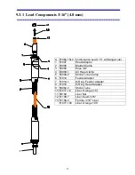
Refer to drawing in (SECTION 9.3.1)
Remove combination leads (50062-13 cable assembly) from wire feeder; Lay the cable
assembly out flat and straight. Then remove liner nut (50109), insert (50018-A) and
ferrule (51109-2), this will expose the existing liner to allow it to be removed by pulling
the liner out of the cable assembly.
Replace/install
the outer liner (
violet
) by first rounding the outer edge of the tubing with
a file, this will allow the liner to slide freely through the leads, then making sure the
assembly is straight, push the liner through the assembly until it reaches and seats into the
spray head adapter (51007). Replace ferrule and liner nut, then push liner into cable
assembly, eliminating any slack, cut off liner about 1 1/2” (37 mm) from end of feeder
adapter fitting and replace liner insert and tighten the liner nut. Verify the position by
looking down the end of the spray head adapter - the liner should be visible about an inch
and a quarter (32 mm) from the end.
IMPORTANT
- The liner must be seated in the spray head adapter (as shown below) to
allow smooth wire flow and to obtain the required
air seal
.
After the outer liner has been installed into both leads, place the head onto the leads.
Now install the inner (red) liner by first, rounding the outer edge of the tubing with a file.
Then push the red liner into the outer liner until it butts against the contact tube holder,
mark the red liner where it is even with the purple liner, then pull it back and cut it off
about 3/8” (9.5 mm) shorter than the mark. Now place the ferrule onto the purple hose,
install the liner insert by threading onto the red hose, it should thread about ¼” (6.4mm),
now install all head parts and complete the head assembly.
Содержание BRIDGEMASTER
Страница 20: ...7 3 System Assembly drawing shows optional straighteners...
Страница 30: ...17 6 2 1 Angle Spray Nozzle 3 16 4 8 mm Wire Head...
Страница 31: ...18 6 3 Air Nozzle Alignment 1 8 3 2 mm Wire Head...
Страница 32: ...19 6 3 2 Angle Spray Nozzle 1 8 3 2 mm Wire Head...
Страница 57: ...44 9 4 1 System Wiring...

