


Rev.2.1 08/03/04
6
INSTALLATION
1. Check power supply. (See Section “Before Installation 3a”)
2. Disconnect power before beginning.
3. Mounting Instructions
a. To mount Haloguard
II/IR controller:
1. Install No. 10 x 1” screw at approximate center of desired location. Slip controller over
fastener head.
2. Remove lower cover to expose lower circuit board. Install two additional fasteners
through holes provided beneath lower cover.
b. To mount IR Sensor Module
1. Mount IR Module in a
VERTICAL
position in a location not subject to vibration or
extreme temperature fluctuation. Remove cover. Secure with No. 8 x 1” (min.) screws
through (4) holes beneath cover or use mounting feet provided. Extend sample tubing to
18-24” above floor, terminate with end of line filter.
2. Inlet/Exhaust Extension (optional) may be used to extend sample point up to 200FT with
0.125”OD x 0.093”ID nylon, copper, or stainless steel tubing. When extending tubing:
a. Keep sample lines as short as possible and free of kinks.
b. Attach 30 micron Inlet Filter at sample point.
c. Exhaust to atmosphere.
DO NOT
install any device which might restrict the flow.
Refer to FIGURE 3 - Controller Lower Circuit Board before proceeding.
DO NOT CUT SUPPLIED CABLE
Maximum Extension length 1000 Feet.
4. Connecting Haloguard
II/IR Controller and IR Sensor Module
a.
Wiring Instructions using supplied cable without extension
:
1. Eight feet (8FT.) of cable with DIN connectors is supplied. Connect cable from
Haloguard
II/IR Controller to IR Sensor Module location
Refer to Figures 2 and 3 before proceeding.
b.
Wiring Instructions using cable with extension
:
1.
We recommend 3 conductor 18 ga. cable with foil shield, Carol C0455 or equal. Use 3/4”
conduit if required
.
. 2. Haloguard
II/IR Controller is provided with 18” cable with DIN Connector and IR
module is provided with 6
1/2
’ cable. To extend sensor beyond the provided length, remove
18” cable with DIN connector from controller Lower Circuit Board. Splice or solder
extension cable to end of 18” cable. Reconnect extended sensor cable to terminal block in
lower circuit board of controller.
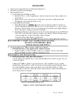
Terminal
Provided
Wire Color
Extension
Wire Color
Function
T1
Red
Red
See Note
T2
White
White
Signal
T3
Blk./Blk
Black/Shield
Ground
Note: T1 Used with Oxygen Sensors Only.
Figure 6 - Sensor Cable Terminal Connection