


2 Rev.2 07/26/98
IMPORTANT
READ ENTIRE BOOKLET BEFORE
INSTALLING OR OPERATING
HALOGUARD
TM
II/IR MONITOR
TABLE OF CONTENTS
Page
1. Unpacking Instructions
3
2. Before Installation
3
3. Installation
6
a. Standard Cable Installation
6
b. Extended Cable Installation
7
4. Calibration
9
5. Testing
10
6. Trouble Shooting
10
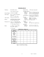
7. Specifications
11
FIGURES
Page
1. Dimension Drawing
4
2. Haloguard
II/IR Controller Upper Circuit Board
5
3. Haloguard
II/IR Controller Lower Circuit Board
5
4. Relay Junction Box Connections
5
5. LCD Display Features
5
6. Sensor Cable Terminal Connectors
6
7. IR Module Circuit Board
7
8. Alarm Jumper Settings
8
9. Exposure Limits
8
10. Function Jumper Settings
8
11. Initial Factory Settings
11
12. Wiring Diagram
12