


1800 Hurd Drive ● Irving, Texas 75038 ● (972) 580-0200 ● (888) 580-0202 ● Fax (972) 580-0277
URL: www.thermal-edge.com ● Email:
SP-ENG-211-D48-02 Rev 2.3 13 |
P a g e
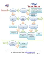
System Faults
If any of the critical control parameters exceed limits, the compressor is turned off and an alarm
condition is indicated on the front panel.
There are three main conditions that can shut the AC compressor down:
The condenser high temperature alarm
The evaporator coil alarm
The compressor thermal overload
In the event that the condenser coil overheats, a condenser high temperature alarm,
HA2
, will flash on
the display of the digital temperature controller and the compressor will turn off after a 3 minute time
delay.
In the case that the evaporator coil ices up or there is a leak, an evaporator coil alarm,
CA
, will flash
on the display of the digital temperature controller and the compressor will turn off after a 2 minute
time delay.
A thermal overload protects the compressor against faults. In the event that the snowflake status LED
is on, but is not flashing, and the compressor is not running, an internal fault may have occurred.
Refer to the Troubleshooting Guide in this manual.
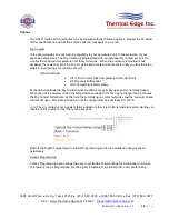
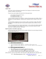
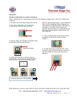
Digital Temperature Controller Programming
For the end user this section will provide all the necessary information to view and change all functions
and parameters available to you.
HOW TO SEE THE SETPOINT
……..
1.
Press and immediately release the
SET
key. The display will show the setpoint value.
2.
Press and immediately release the
SET
key or wait for 15 seconds to display the enclosure temperature
again.
HOW TO CHANGE THE SETPOINT
……..
1.
Press the
SET
key for more than 2 seconds to change the setpoint value.
2.
The value of the setpoint will be displayed and the
“F”
LED starts blinking.
3.
To change the
SET
value, press the
UP
or
DOWN
arrow key within 15 seconds.
4.
To store the new setpoint value, press the
SET
key again or wait 15 seconds.
Note:
The set value is stored even when the procedure is exited by waiting for the time -out to expire.


