Manual 0-2583
31
SERVICE
4. Remove the torch head from the leads (refer to Sec-
tion 5.06, Servicing Machine TorchComponents or
Section 5.07, Servicing Hand Torch Components).
5. With the torch head disconnected from the leads,
measure the resistance between negative cathode
body of the torch head (where the electrode seats)
and the positive anode body of the torch head (the
outer threads where the shield cup seats).
Infinite resistance (no continuity) should be mea-
sured between negative and positive sections of
the torch head.
If any current can flow through the center insula-
tor, the torch head is faulty and must be replaced.
If the torch head is okay, the problem is in the leads
assembly. Proceed to paragraph "B' to check torch
lead assembly.
B. Checking Torch Lead Assembly
Check the torch leads by measuring the resistance be-
tween the positive pilot lead connector and the negative/
plasma lead fitting.
If continuity is found, replace the torch leads.
If no continuity is found, the torch leads are probably
good. The torch leads should be tested further for insu-
lation breakdown if no other fault can be found. To test
the torch leads for insulation breakdown use the follow-
ing procedure:
WARNINGS
This procedure should be performed only by a quali-
fied electronic technician.
a. Remove the shield cup, tip, gas distributor, and
electrode from the torch head assembly if not al-
ready done.
b. Connect a Hi-Pot Tester capable of producing
2500VAC between the positive pilot lead and the
plasma (negative) lead fittings.
c. Increase the output of the Hi-Pot Tester to a maxi-
mum of 2500VAC.
If the voltage drops to 0VAC then the insulation be-
tween the torch leads is breaking down and the leads
must be replaced.
Carefully reassemble the components and recheck the
completed assembly per paragraph 'A', Step 3 to confirm
that the components have been properly assembled.
This completes the checks for the proper operation of the
center insulator of the torch head and leads. Proceed to
paragraph 'C' to check pilot and switch control wires..
C. Checking Pilot and Switch Control Wires
1. Disassemble the torch head and leads to expose
the torch head connections. Refer to Section 5.06,
Servicing Machine Torch Components or Section
5.07, Servicing Hand Torch Components.
2. Visually check that the PIP wires, torch switch wires,
pilot lead connection, and negative/plasma lead
connections are properly connected and in good
condition (no shorts or arcing).
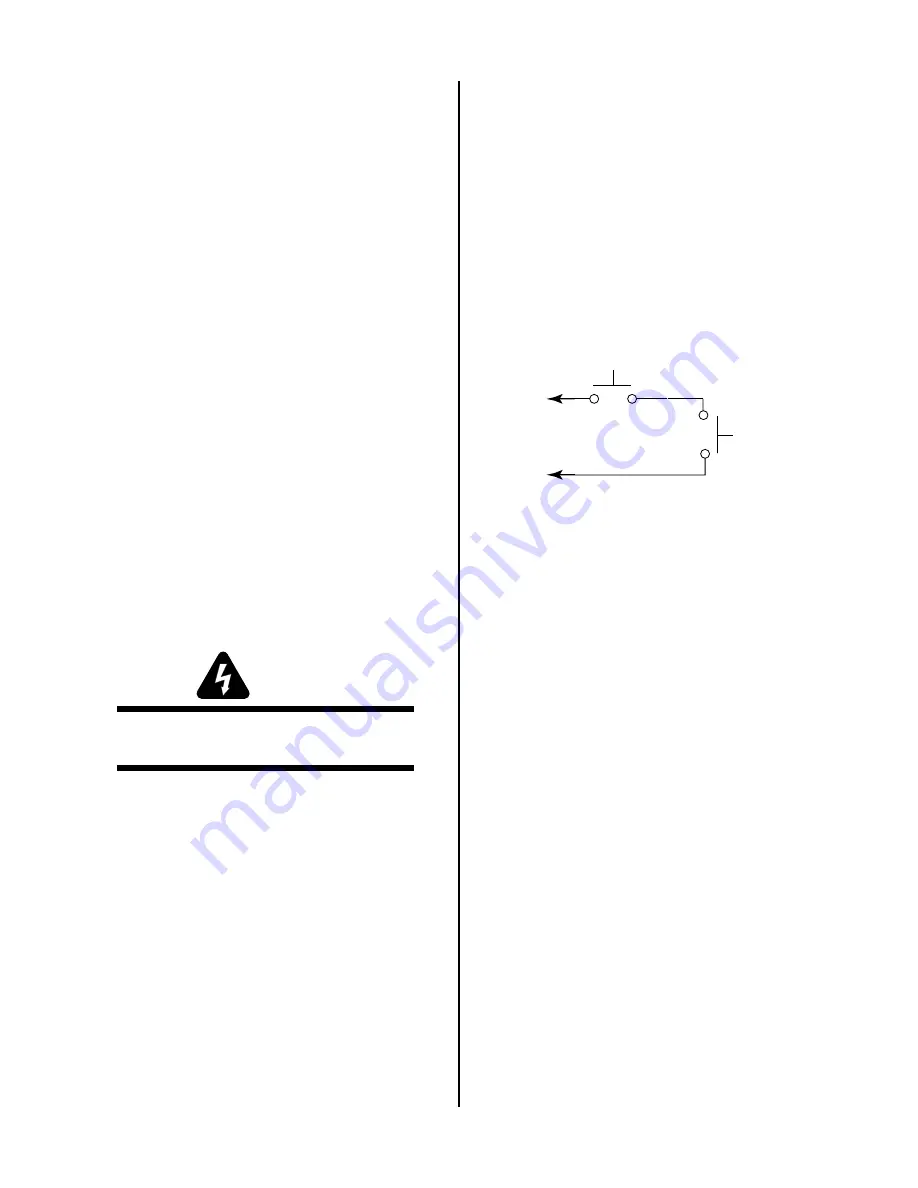
A-00458
Torch Switch
PIP Pin
PIP Pin
Shield Cup
To Control
Cable Wiring
Figure 5-9 Torch Switch and PIP Schematic
If problems are evident, repair or replace as re-
quired.
If there are no visual problems then proceed to
Step 3.
3. Check the pilot and switch control wires for opens
from one end of the torch leads to the other.
If open replace torch leads.
4. Check the pilot and switch control wires for shorts
to other components in the torch leads.
If shorted then replace torch leads.
5. Carefully reassemble the torch and leads.
D. Torch Leads Replacement
1. Disconnect the torch gas, pilot control wire and
torch control cable connections from the power
supply.
2. Pull the defective leads from the power supply.
3. Remove the torch head assembly as described Sec-
tion 5.06 Servicing Machine Head Components,
or Section 5.07 Servicing Hand Torch Components.
5. Connect the replacement torch lead gas, pilot con-
trol wire and torch control cable connection to the
power supply.
7. Install the torch head assembly onto the replace-
ment leads.
Содержание PCH-100XL
Страница 2: ......
Страница 6: ......
Страница 18: ...INTRODUCTION DESCRIPTION 12 Manual 0 2583...
Страница 22: ...INSTALLATION PROCEDURES 16 Manual 0 2583...
Страница 38: ...SERVICE 32 Manual 0 2583...


