20
Menu 1 – Capacity Control Setup
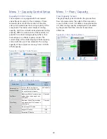
Capacity Control Screen
The compressor is equipped with four solenoid
valves flange mounted to the compressor. These
solenoid valves control the location of the slide
valve, which determines the cooling capacity of the
compressor. The loader valve increases cooling
capacity, and three unloader valves decrease cooling
capacity. With the combination of these valves, it is
possible to control cooling capacity either in four
finite stages or in infinite capacity control. The
current setup of the chiller employs infinite capacity
control with the use of two solenoids. The cooling
capacity of the compressor can vary from 25-100%
of full capacity.
Figure 29 – Capacity Control Screen
Table 12 - Capacity Control Parameters
Menu Item
Description
Default
Value
Automatic or
Manual Mode
In Auto Mode, the control
system adjusts the slide valve
for optimum performance.
AUTOMATIC
Fast Rate
Maximum Delay Time between
pulses when the demand is at
its highest
3 Seconds
Slow Rate
Minimum Delay Time between
on pulses when the Demand is
at its lowest
7 Seconds
Kp
Proportional PID value
3
Ti
Integral PID value
1500
Td
Derivative PID value
0
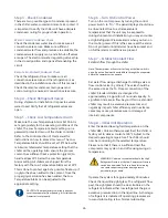
Menu 1 – Flow / Capacity
Flow/Capacity Screen
The graph displays trend data for the process fluid
flow rate measured at the outlet of the evaporator
on each chiller circuit. In addition, an approximation
of chiller cooling capacity is displayed as calculated
by the process fluid flow rate and temperature
difference.
Figure 30 – Flow / Capacity Screen


