background image

(2)  Attach your WiFi module to your  

       Basement Watchdog system  


(see diagram sheet for visual help)

Note: The WiFi module must receive 115V AC +/- 5% and 
60 Hz from the AC outlet to function correctly

2A. Attaching your WiFi module to your Basement  

      Watchdog backup system with a USB port       

This section will explain how to connect your WiFi module 
to your backup sump pump system using the included 
micro USB cable.  Using the micro USB cable will provide 
a specific notification email explaining exactly which 
alarm is activated on the system it is connected to.  This 
connection style is only compatible with CONNECT models 
which include a USB port. 

 
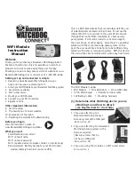
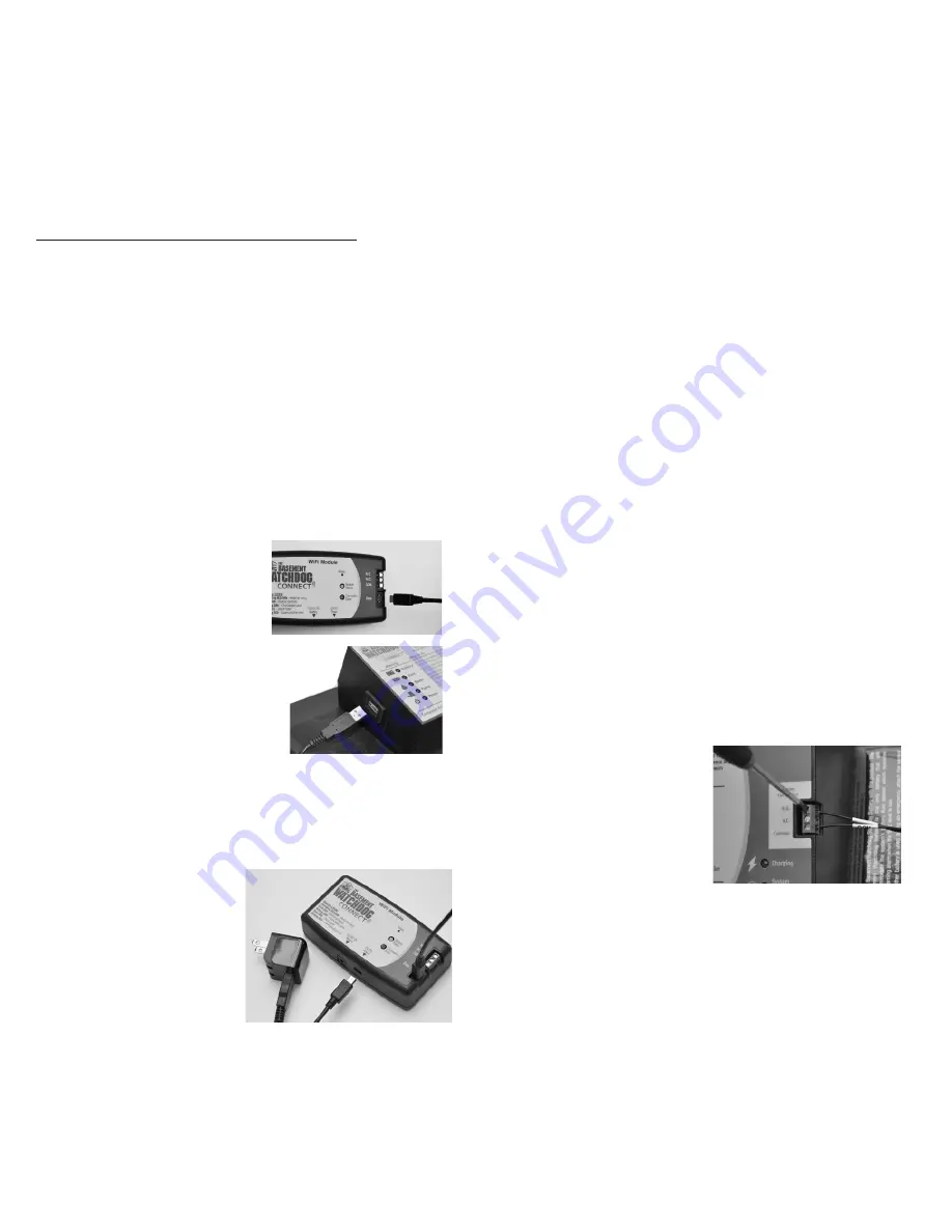
1.  Using the Micro USB cable.   
  Connect the micro end into  
  the Data port located on the  
  front of the module in the  
  lower right corner.

2.  Connect the standard USB  
  end into the USB port on    


  the backup sump pump  
 controller

Note: When using the data connection, no other cable 
is necessary; this cable will also power the WiFi module.  
However, we recommend connecting the mini USB cable and 
USB charger in order to provide an additional power source 
to the WiFi module.

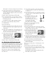
3.  Connect the USB   
  charger to the WiFi  
  module using the  
  included mini USB  
 cable

4.  Plug the other end of  
  the USB charger into your power outlet

5.  The red and green lights on the WiFi module should  
  start alternating
  (a)  This means that it is ready for setup

Note: In order to receive notification during a power outage, 
you must have a Wi-Fi router / modem with a built-in 
battery backup or an uninterruptible power supply (UPS) 
powering the equipment.

Proceed to section 5 (Mounting your WiFi module)

2B. Attaching your WiFi module to your Basement  

      Watchdog backup system with a remote terminal

This section will explain how to connect your WiFi 
Module to your backup sump pump system using the 
remote terminal and the included remote terminal cable.  
Using the remote terminal cable will provide a general 
notification stating that your system is alarming.  This 
connection style is compatible with all models that 
include a remote terminal.  

Note: This connection style should not be used if your 
backup is a Basement Watchdog Connect and has a USB 
port.  You will only connect via the USB port.

Note: you will not receive remote notification for low fluid 
in the battery when using the remote terminal connection.

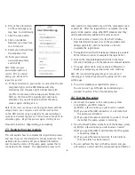
1.  Using the 3 foot remote  
  terminal cable, attach  
  one end of the cable  
  labeled ‘NO’ to the  
  Normally Open port  
  labeled ‘NO’ on the  
  back or side of the  
  backup system control box.  Turn the screw clockwise  
  to secure the wire.

2.  On the same end of the remote terminal cable,    
  attach the cable end labeled ‘COM’ to the Common  
  port labeled ‘COM’ on the back or side of the backup  
  system control box.  Turn the screw clockwise to  
  secure the wire.

2

Содержание BW-WIFI

Страница 1: ... battery built into router or UPS This is a Wi Fi based device that can remotely alert the user of potential water problems in their home It will use the internal Wi Fi chip to connect to the user s Wi Fi network through their router When connected to a backup sump pump system it will send an email or a text message to the user s phone or other device when there is a potential problem with the con...

Страница 2: ...ights on the WiFi module should start alternating a This means that it is ready for setup Note In order to receive notification during a power outage you must have a Wi Fi router modem with a built in battery backup or an uninterruptible power supply UPS powering the equipment Proceed to section 5 Mounting your WiFi module 2B Attaching your WiFi module to your Basement Watchdog backup system with ...

Страница 3: ...of the wire into the 12V 6V DC Battery port on the bottom of the Module Note In order to receive notification during a power outage you must have a Wi Fi router modem with a built in battery backup or an uninterruptible power supply UPS powering the equipment Proceed to section 5 Mounting your WiFi module 3 Accessories When connected using a USB port it is possible to add a high water detector usi...

Страница 4: ...e to check the Used as High Water Alarm checkbox in the Devices tab of the WiFi Modules page See section 9 1 C a If you will be using this in a sump pit sewage pit or other area that can handle a 3 8 depth proceed to Section 4 1 b If you will be using this in an area where you need to know when there is minimal buildup of water proceed to Section 4 2 1 If you will be using this in a sump pit sewag...

Страница 5: ...would like to mount the module within 3 feet of the backup Top of the battery box Top of the backup control box To the wall 2 Using the included 6 Pan Head screws mount the module to the wall or stud a Install the screws into the wall or stud 3 inches apart b Mount the module to the screws using the keyhole screw mount on the back of the module Proceed to Section 6 Connect to your Wi Fi network 6 ...

Страница 6: ...After the registration is complete the same email can be used to setup other WiFi modules and they will be automatically added to the same account 1 You will receive an email in a few short minutes from GlentronicsConnect com at the provided email address email 1 with instructions on how to complete the registration 2 The registration email will include your temporary password Write it down in ord...

Страница 7: ...erminals or used as a WiFi water alarm 2 The Profile tab to the User Profile page This page will store the user s information and can be edited at any time This page is also used to change the password Changing the provided temporary password to your own is recommended after registration is complete 3 The Status tab to the Status page This page will display the status of the unit that is connected...

Страница 8: ... this mode c The next user will register the module to their email address Warning Changes or modifications not expressly approved by Glentronics could void the user s authority to operate the equipment Troubleshooting This section will explain how to troubleshoot any problems Problem Red light is on steady The red green lights keep alternating after the setup process Green light is steady red lig...

Страница 9: ...f sale or receipt to the address listed below GLENTRONICS INC at its option will either repair or replace the product and return it postage prepaid What is NOT covered by this warranty This warranty does not cover the cost or value of damaged property including expressly any property that has been affected by water overflow seepage or flooding If GLENTRONICS INC determines that a product is deemed...

Страница 10: ...n experienced radio TV technician for help Contains FCC ID W7OMRF24WG0MAMB To satisfy FCC RF Exposure requirements for mobile and base station transmission devices a separation distance of 20 cm or more should be maintained between the antenna of this device and persons during operation To ensure compliance operation at closer than this distance is not recommended The antenna s used for this trans...

Отзывы: