Texmate, Inc. Tel. (760) 598-9899 • www.texmate.com
DL-40JANUS-DCA/DCV manual (d0114)
Page 9
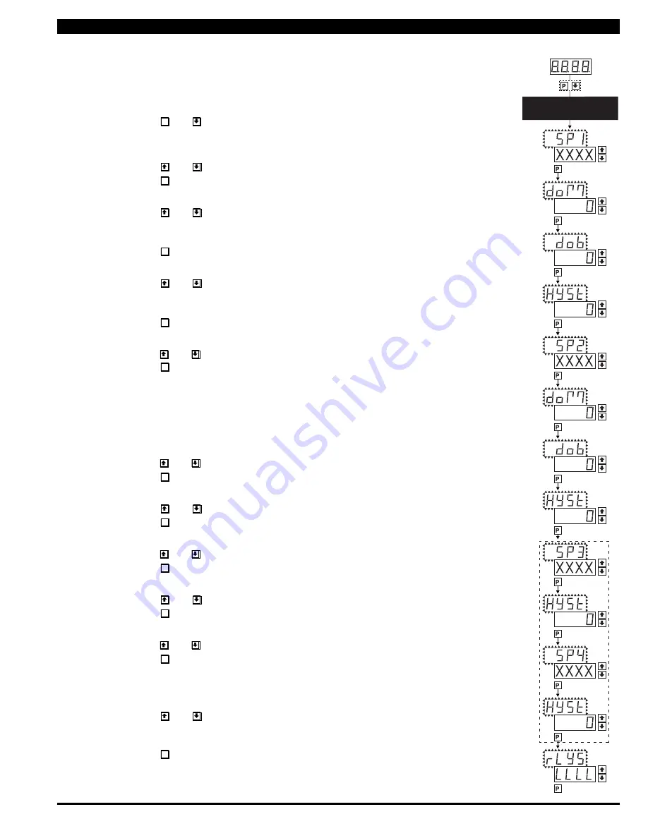
The following programming steps are required to enter the setpoint values and configure the relay
functions in a meter with four relays using four setpoints. Generally if less than four relays are
installed the software auto detects missing relays and deletes reference to them from the menu. In
some cases setpoints without relays are operational for display only purposes.
STEP A Enter the Setpoint Mode
1) Press the
P
and buttons at the same time.
Display toggles between [SP1] and the previous [SP1] setting.
STEP B Set Setpoint 1 (SP1)
1) Using the and buttons, adjust the display to the desired SP1 value.
2) Press the
P
button. Display toggles between [doM] and the previous [doM] setting.
STEP C Set the SP1 Delay-on-Make (doM) Delay Time Setting
1) Using the and buttons, adjust the display to the desired [doM] value
(0 to 9999 seconds). The reading must continuously remain in an alarm condition
until this delay time has elapsed before the relay will make contact (energize).
2) Press the
P
button. Display toggles between [dob] and the previous [dob] setting.
STEP D Set the SP1 Delay-on-Break (dob) Delay Time Setting
1) Using the and buttons, adjust the display to the desired [dob] value (0 to 9999
seconds). The reading must continuously remain in an non-alarm condition until this
delay time has elapsed before the relay will break contact (de-energize).
2) Press the
P
button. Display toggles between [HYSt] and the previous [HYSt] setting.
STEP E Set the Hysteresis Setting for Setpoint 1
1)
Using the and buttons, adjust the display to the desired hysteresis [hYSt] value.
2) Press the
P
button. Display toggles between [SP2] and the previous [SP2] setting.
NOTE: Half of the Hysteresis value selected is applied above and below the setpoint.
NOTE: Steps F, G, H and J have functionally the same procedure as steps B, C, D, and E shown above.
STEP F Set Setpoint 2 (SP2)
STEP G Set the SP2 Delay-on-Make (doM) Delay Time Setting
STEP H Set the SP2 Delay-on-Break (dob) Delay Time Setting
STEP I Set the Hysteresis Setting for Setpoint 2
1)
Using the and buttons, adjust the display to the desired hysteresis [HYSt] value.
2) Press the
P
button. Display toggles between [SP3] and the previous [SP4] setting.
STEP J Set Setpoint 3 (SP3) (No [doM] or [dob])
1) Using the and buttons, adjust the display to the desired SP3 value.
2) Press the
P
button. Display toggles between [HYSt] and the previous [HYSt] setting.
STEP K Set the Hysteresis Setting for Setpoint 3
1)
Using the and buttons, adjust the display to the desired hysteresis [HYSt] value.
2) Press the
P
button. Display toggles between [SP4] and the previous [SP4] setting.
STEP L Set Setpoint 4 (SP4) (No [doM] or [dob])
1) Using the and buttons, adjust the display to the desired SP4 value.
2) Press the
P
button. Display toggles between [HYSt] and 0.
STEP M Set the Hysteresis Setting for Setpoint 4
1)
Using the and buttons, adjust the display to the desired hysteresis [HYSt] value.
2) Press the
P
button. Display toggles between [rLYS] and the previous relay setting.
STEP N Set Relay Activation mode [rLYS]
(H) High the relay energizes when the setpoint is exceeded. (L) Low the relay energizes
below the setpoint. The setpoint is indicated from left to right SP1, SP2, SP3, SP4.
1) Using the and buttons, adjust the reading on the display to the desired
relay settings: [LLLL], [LHLH], [HLHL], [HHHH].
If only 2 relays installed [LH--], [HL--], [HH--], [LL--].
2) Press the
P
button.
The meter exits the setpoint mode and returns to the operational display.
The Setpoint Relay programming mode is now complete.
Setpoint Setting and Relay Configuration Mode
SETPOINT SETTING AND
RELAY CONFIGURATION MODE
See Page 9
STEP B
Set
Setpoint 1 (SP1)
STEP C
Delay on
Make (doM)
STEP D
Delay on
Break (dob)
STEP F
Setpoint 2
(SP2)
STEP E
Hysteresis
(HYSt)
STEP I
Hysteresis
(HYSt)
STEP K
Hysteresis
(HYSt)
STEP M
Hysteresis
(HYSt)
STEP N
Relays
Activation [rLYS]
Confirm
STEP G
Delay on
Make (doM)
STEP H
Delay on
Break (dob)
STEP J
Setpoint 3
(SP3)
NOTE: [dob] [dom]
Functions are
only available for
SP1 and SP2
STEP L
Setpoint 4
(SP4)
MAIN MENU
Operational Display
STEP A
[LHLH]
[HLHL]
[HHHH]


