Page 3
CL-B101D40RPM(d0097) manual
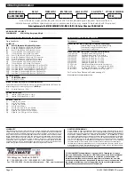
The CL-B101D40RPM is an intelligent bargraph meter with a hier-
archical software structure designed for easy programming and
operation, as shown below in the software logic tree.
Software Logic Tree
Peak
[PEAK]
Reset
PEAK
Reset
VALY
Valley
[VALY]
[orAn]
[rEd]
NOTE: Will only
appear if a tricolor
display is installed
[orAn]
[rEd]
[orAn]
[rEd]
[orAn]
[rEd]
[orAn]
[rEd]
BARGRAPH COLOR
PROGRAMMING MODE
See Page 9
Tricolor Bargraph
The tri-color bargraph is
designed like a traffic light, to
display either red, orange or
green, but only one color at a
time. The color to be displayed
is selected in two ways.
The first step is to select the
color to be displayed when the
bar is “below” whichever set
point is set to the lowest
position.
The second step is to select the
color to be displayed when the
bar is above each specific
setpoint, regardless of the order
or position to which the set
points are set.
However, if two or more
setpoints with differently
specified colors are positioned
at the same set point value, the
color specified for the set point
with the highest identifying
number will be displayed. When
setpoints are set to the same
value, the SP4 color overrides
the SP3 color, the SP3 color
overrides the SP2 color, and the
SP2 color overrides the SP1
color.
Set Setpoint 1
[SP1]
Delay-on-Make
[doM]
Delay-on-Break
[dob]
Relays
Activation
[rLYS]
(h) High the
relay
energizes
when the
setpoint is
exceeded.
(L) Low
the relay
energizes
below the
setpoint.
Setpoint 2
[SP2]
Setpoint 2
[SP2]
Setpoint 1
[SP1]
Setpoint 3
[SP3]
NOTE: [dom] [dob]
Functions are only
available for SP1
abd SP3
0 to 9999
seconds
0 to 9999
seconds
Hysteresis
[hYSt]
Hysteresis
[hYSt]
Bar Color
[coL]
Hysteresis
[hYSt]
Hysteresis
[hYSt]
Setpoint 3
[SP3]
Setpoint 4
[SP4]
Setpoint 4
[SP4]
Operational Display
MAIN MENU
PEAK & VALLEY
VIEW & RESET
BRIGHTNESS AND
SETPOINT VIEW MODE
Bargraph Center Point
Display Selection [cto]
This branch will
only appear if
the analog
output option
is installed
Back to
Operational
Display
Digital Display
ON/OFF
Selection [diSP]
Sub-menu MODE
Calibration Mode
Calibration
Input
Calibration
Output
Calibrate Analog
Output Low
[cLo]
Calibrate Analog
Output High
[chi]
Select the Digital
Reading at which
the Analog Output
Hi [chi] will occur
Select the Digital
Reading at which
the Analog Output
Lo [cLo] will occur
This branch will only appear
if the analog output option
is installed
DIGITAL SPAN SELECTION
FOR ANALOG RANGE OUTPUT
See Page 6
DIGITAL DISPLAY ON/OFF
See Page 6
BARGRAPH CENTER POINT
DISPLAY MODE SELECTION
See Page 6
TWO POINT ANALOG OUTPUT
RANGE SETTING AND CALIBRATION
See Page 7
Bargraph Display
Scale Lo Range
Setting [bLo]
Bargraph Display
Scale hi Range
Setting [bhi]
DIGITAL SPAN SELECTION
FOR BARGRAPH DISPLAY
See Page 5
Goes directly
to Zero setting
if Analog Output
is not installed
PULSES PER
REVOLUTION, RANGE
SELECTION
+
–
4.00
+
–
20.00
1 Dimmest
2 Dim
3 Bright
4 Brightest
SETPOINT SETTING AND
RELAY CONFIGURATION MODE
See Page 8
L or h
L or h
L or h
L or h
Display
Brightness
[br]
Delay-on-Make
[doM]
Delay-on-Break
[dob]
0 to 9999
seconds
0 to 9999
seconds
Sub-menu MODE
Software Version is Displayed on Power-up
When power is applied, all segments of the bargraph and dig-
ital display light up for 3 seconds. The version number of the
installed software is then displayed for 2 seconds, after which,
the operational display indicates the input signal.
15 Second Program Timeout
Except for ZERO and SPAN settings in the Two Point Digital Calibration Mode
and the Analog Output Range Setting and Calibration Mode (cLo and chi), the
meter has a 15 second program timeout. If no buttons are pressed for 15
seconds in any of the other programming sequences, the meter will exit the
programming mode and return to the operational display. Any program chang-
es that were made prior to pressing the
P
button in the preceding step will
not be saved.


