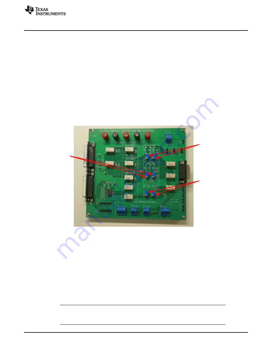
Use these trim pots to
adjust RTD_Min value
Use these trim pots to
adjust RTD_Mid value
Use these trim pots to
adjust RTD_Max value
Software Overview
37
SBOU123A – March 2012 – Revised September 2016
Copyright © 2012–2016, Texas Instruments Incorporated
XTR108EVM-USB Evaluation Board and Software Tutorial
5.3.1
Step 1: Initialize
Before calibration can take place, a model file must be loaded into the software. The XTR108EVM-USB
software automatically loads the most recent model file into memory at startup, but a different model file
can be selected by clicking the
Load Model File
button. The path of the loaded model file is shown in the
Model File
indicator.
After loading a model file, use the channel-to-calibrate control to select which channel should be
calibrated. Disabled channels in the model file are grayed out and unable to be selected. After selecting a
channel to calibrate, click the
Calculate Initial Settings
button to write the initial configuration to the
XTR108 and EEPROM.
5.3.2
Step 2: Set RTD Emulator
The next step in the calibration procedure is to set the XTR108EVM-USB Interface Board RTD Emulator.
Once the
Calculate Initial Settings
button is pressed in
, the
Set RTD_Min
,
Set
RTD_Mid
, and
Set RTD_Max
buttons are enabled and the calculated resistance values for each channel
are displayed. As shown in
, the resistance value of each RTD Emulator channel can be set by
adjusting the trim pots of each channel with a small flat-head screwdriver.
Figure 25. Adjust RTD Emulator
Click the
Set RTD_Min
button to set the resistance of the RTD_Min channel. This button configures the
XTR108EVM-USB Interface Board to route the RTD_Min resistance to the DMM through the multimeter
connect terminals. Configure the DMM for four-wire resistance (
Ω
4W) measurement, then adjust POT1
(coarse) and POT2 (fine) until the resistance measured by the DMM matches the value shown by the
RTD_Min
indicator in the XTR108EVM-USB software.
Next, click the
Set RTD_Mid
button to set the resistance of the RTD_Mid channel. Adjust POT3 (coarse)
and POT4 (fine) until the resistance measured by the DMM matches the value shown by the
RTD_Mid
indicator in the XTR108EVM-USB software.
Finally, click the
Set RTD_Max
button to set the resistance of the RTD_Max channel. Adjust POT5
(coarse) and POT6 (fine) until the resistance measured by the DMM matches the value shown by the
RTD_Max
indicator in the XTR108EVM-USB software.
NOTE:
If the 34401A multimeter is connected to the PC by the NI GPIB-USB-HS controller, the
XTR108EVM-USB software automatically configures the 34401A for four-wire resistance
measurement.


