Setup
3.
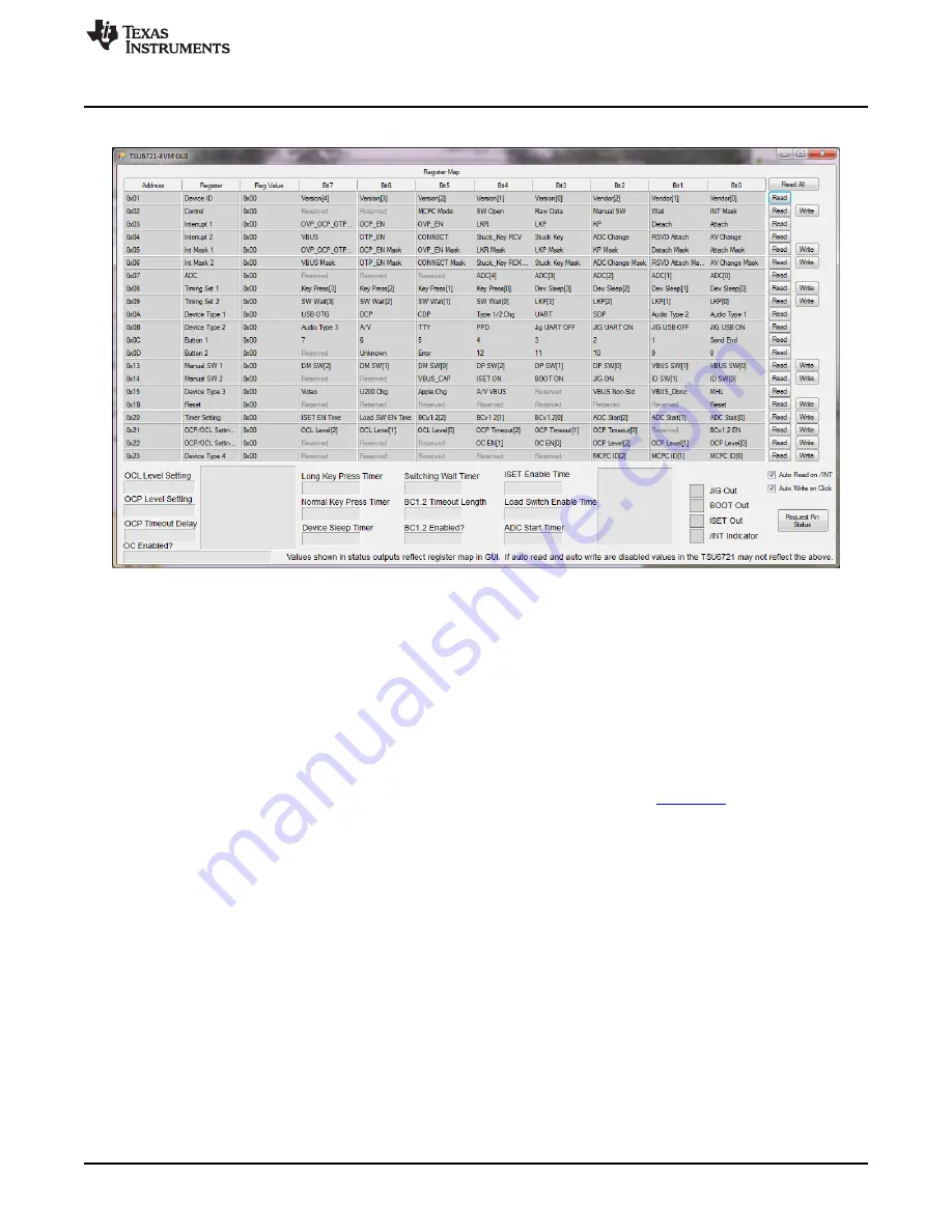
The GUI looks like
when it is opened and the LaunchPad is connected:
Figure 4. TSU6721EVM GUI Without LaunchPad
3.4
Getting Started Using the TSU6721 Micro-USB Switch EVM
3.4.1
Evaluating the TSU6721EVM without the GUI
1. The TSU6721EVM can be powered with or without the LaunchPad. If you have a LaunchPad available
and have completed steps 1–3 in
, continue to step 2. If you do not have a LaunchPad,
attach the jumper on J2 from VBAT to EXT, and attach jumper on J4 to VDDIO to EXT. Next, apply 3
V to 4.4 V on J1 and apply 1.65 V to 3.6 V on J3.
2. Connect a 150-k
Ω
resistor between ID (J17) and GND (TP1, TP2, or TP3). By default, the TSU6721
closes the appropriate switches as specified in Table 2 of the TSU6721 (
) datasheet.
3. While referencing the on-resistance values for each signal path in the TSU6721 datasheet, measure
the following resistance values to verify that the switches have been closed:
(a) DM (J14) to TxD (J19)
(b) DP (J13) to RxD (J19)
4. Remove the 150-k
Ω
resistor.
5. Attach a micro-USB cable from the PC to J15 on the TSU6721EVM. As most PCs are considered USB
Standard Downstream Port (SDP) or Charging Downstream Port (CDP) chargers, the TSU6721 closes
the appropriate switches as specified in Table 4 on the TSU6721 datasheet.
6. While referencing the on-resistance values for each signal path in the TSU6721 datasheet, measure
the following resistance values to verify that the switches have been closed:
(a) DM (J14) to DM_HT (J11)
(b) DP (J13) to DP_HT (J10)
7. Remove the micro-USB cable from the PC.
8. Choose any desired charger type or ID resistor specified in either
Table 2
or
Table 4
of the TSU6721
datasheet to observe the behavior of the TSU6721 switch. The datasheet describes the switch
behavior for each condition.
9
SLVUA77 – May 2014
TSU6721EVM Micro-USB Switch Evaluation Module
Copyright © 2014, Texas Instruments Incorporated


