Texas Instruments MCT8317 Скачать руководство пользователя страница 9

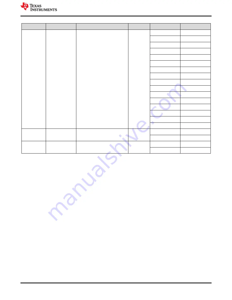
Table 4-2. Description of User-Selectable Settings on MCT8317EVM (Default in Bold) (continued)

Designator

Setting Name

Description

Layer

Position

Function

J6

MSP to MCx Shunt 

jumper bridge

Connects signals from MCU and 
user switches to MCx8316A when 
jumpers are inserted

Top

NC

NC

DIR_SW

DIR

BRAKE_SW

BRAKE

SPEED_IN

SPEED/WAKE

MSP_SOMI/SCL

MCx_SCL

MSP_SIMO/SDA

MCx_SDA

MSP_CLK

NC

MSP_STE

NC

MSP_A3

DACOUT2/SOX

MSP_A2

DACOUT2

MSP_A1

DACOUT1

MSP_ALARM

ALARM

MSP_nFAULT

nFAULT

MSP_FGOUT

FGOUT

NC

NC

AGND

AGND

S1

BRAKE

Turns on all low-side MOSFETs

Top

Left

Brake enabled

Right

Brake disabled

S2

DIR

Controls direction of motor

Top

Left

ABC

Right

ACB

5 Hardware Setup

The hardware required to run the motor is the MCT8317EVM, a Micro-USB cable, and a power supply with a DC 
output from 4.5-V to 20-V. Follow these steps to start up the MCT8317EVM:

1. Connect the DC power supply to header J7. Connect to VBAT and PGND to apply reverse polarity protection 

and the pi filter to the EVM. Otherwise, connect to VM and PGND to bypass the reverse polarity protection 
and pi filter.

2. Apply user configurable jumper settings. See 

Section 4.5

 section for more information.

3. Flash program into the MCU as described in 

Section 4

. Launch the GUI in GUI Composer and disconnect 

the 4-pin JTAG connections.

4. Connect a Micro-USB cable to the MCT8317EVM and computer.
5. Turn on the power supply and power up the PCB.

If using the MCT8317EVMj with an external microcontroller, remove all shunt jumpers from jumper bridge J6. 
Connect with external jumpers to the left side of the jumper bridge from the external MCU.

6 MCT8317A GUI Application

The MCT8317EVM includes a USB-UART interface, using a MSP430FR2355 microcontroller, that serves as a 
communication bridge between a host PC and the MCT8317 device for configuring various device settings and 
reading fault diagnostic information. A MCT8317A GUI is available to interface with and configure the MCT8317 
using this communication interface.

Access the 

MCT8317A GUI

 through the TI Cloud Gallery.

6.1 Running the GUI

The MCT8317A GUI can be run directly inside a web browser (supported in Google Chrome and Firefox).

www.ti.com

Hardware Setup

SLLU360 – DECEMBER 2022

Submit Document Feedback

MCT8317EVM Evaluation Module

9

Copyright © 2022 Texas Instruments Incorporated

Содержание MCT8317

Страница 1: ...nning the GUI 9 6 2 Offline Installer 10 7 MSP430FR2355 Interface Firmware 10 7 1 Downloading Code Composer Studio and Importing MSP430FR2355 Interface Firmware Code 10 7 2 Using the eZ FET to Program the MSP430FR2355 11 8 Schematics 12 8 1 Main Supply and Pi Filter 12 8 2 Connectors and Interface 13 8 3 USB to UART 13 8 4 MCU Programming and Debug 14 8 5 MSP430FR2355 MCU 14 8 6 MCT8317 3 Phase Se...

Страница 2: ...re many user selectable jumpers resistors connectors and test points to evaluate many features of the device and configure device specific settings This document serves as a startup guide to supplement the MCT8317EVM It is intended for engineers to design implement and validate reference hardware for the MCT8317 device Figure 2 1 MCT8317EVM Printed Circuit Board PCB Top View 3 Quick Start Guide Th...

Страница 3: ...lly use the GUI as shown in Section 6 to monitor real time speed of the motor put the MCT8317 into a low power sleep mode and read status of the LEDs Figure 3 1 Reference for Quick Start Guide 4 Hardware and Software Overview 4 1 Hardware Connections Overview MCT8317EVM Figure 4 1 shows the major blocks of MCT8317EVM evaluation module The MCT8317EVM is designed for an input supply from 4 5 V to 20...

Страница 4: ...y protection and Pi filter implemented on the VBAT and PGND terminals To bypass the reverse polarity protection and Pi filter connect the power supply to the VM terminal or VM test point on the board and PGND The three phases of the BLDC motor connect directly to the A B and C terminals of the screw terminal connector J8 provided on the MCT8317EVM Hardware and Software Overview www ti com 4 MCT831...

Страница 5: ... data and 3 3 V power to power the MSP430FR2355 microcontroller The 5 V from the USB power is limited to 500 mA and the 3 3 V from the FTDI chip is limit to 30 mA If the user wishes to supply more current to these rails they may use the 5V_SEL jumper J3 and 3V3_SEL jumper J5 to connect external power rails www ti com Hardware and Software Overview SLLU360 DECEMBER 2022 Submit Document Feedback MCT...

Страница 6: ...355 microcontroller The user can use the Reset RST button at any time to reset and restart the MCU program Two active low LEDs D6 and D7 can be used for debug purposes as well Finally a shunt jumper bridge on the 32 pin connector J6 ties all signals between the microcontroller and MCT8317 These jumpers can be inserted or removed as needed in order to isolate the microcontroller from the gate drive...

Страница 7: ...d Figure 4 5 shows the locations of the LEDs Table 4 1 Description of MCT8317EVM LEDs default in bold after powerup Designator Name Color Description D1 AVDD GREEN Lights up when AVDD is turned ON D2 nFAULT Red Lights up when fault condition has occurred on MCT8317 D3 ALARM Red Lights up when alarm condition has occurred on MCT8317 D4 VM Green Lights up when voltage is applied on VM D6 MSP_LED1 Re...

Страница 8: ...scription Layer Position Function J5 3V3_SEL Select 3 3 V for MCU power Top J5 3V3EXT External J5 3V3COM From FTDI 30 mA J3 5V_SEL Select 5 V for FTDI power Top J3 5V_EXT External J3 5V_USB From USB power 500 mA J1 SPEED_SEL Selects SPEED input source Top J1 EXT External EXT_SPEED test point J1 POT From Potentiometer R4 J1 INT_PWM From internal PWM PWM Duty cycle can be varied by rotating the POT ...

Страница 9: ...rotection and pi filter 2 Apply user configurable jumper settings See Section 4 5 section for more information 3 Flash program into the MCU as described in Section 4 Launch the GUI in GUI Composer and disconnect the 4 pin JTAG connections 4 Connect a Micro USB cable to the MCT8317EVM and computer 5 Turn on the power supply and power up the PCB If using the MCT8317EVMj with an external microcontrol...

Страница 10: ...EXP430FR2355 LaunchPad Development Kit to provide the debug probe Follow the steps below to download the code for the MCT8317EVM to use with the GUI 7 1 Downloading Code Composer Studio and Importing MSP430FR2355 Interface Firmware Code 1 Extract the MCT8317EVM_MSP430FR2355_Firmware_GUI zip to a location on the computer 2 Download the latest version of Code Composer Studio This will set up a ti fo...

Страница 11: ...e pins on J4 of the MCT8317EVM as shown in Table 7 1 and Figure 7 2 3 Connect a micro USB cable to the MSP430 LaunchPad and the PC 4 Click on the Build Project icon or Ctrl B to ensure the project builds successfully Accept any updates if needed from the Console 5 Click on Debug Project to set up a debug session and press the Play button to run the code 6 Stop the debug session close Code Composer...

Страница 12: ...2 BUK9D 23 40EX 330uF C16 bypass RPP PGND VBAT VM Connect to VM to 1 2 3 J7 MOTOR_OUT Reverse Polarity Protection Pi Filter 100V 1uF C17 100V 1uF C24 D8 CDSU101A 1 2 JP1 VM VIN_AVDD SNT 100 BK G VIN_AVDD 1uH L4 4 5 V to 20 V Operation 24V ABS MAX Figure 8 1 Main Supply and Pi Filter Schematic Schematics www ti com 12 MCT8317EVM Evaluation Module SLLU360 DECEMBER 2022 Submit Document Feedback Copyr...

Страница 13: ...e 8 2 Connectors and Interface Schematic 8 3 USB to UART Figure 8 3 USB to UART Schematic www ti com Schematics SLLU360 DECEMBER 2022 Submit Document Feedback MCT8317EVM Evaluation Module 13 Copyright 2022 Texas Instruments Incorporated ...

Страница 14: ... MCU Programming and Debug Schematic 8 5 MSP430FR2355 MCU Figure 8 5 MSP430FR2355 MCU Schematic Schematics www ti com 14 MCT8317EVM Evaluation Module SLLU360 DECEMBER 2022 Submit Document Feedback Copyright 2022 Texas Instruments Incorporated ...

Страница 15: ... BRAKE DIR FG nFAULT AVDD DVDD VM VIN_AVDD AVDD AVDD AVDD SCL SDA 0 R15 0 R16 MCX_SCL MCX_SDA AGND PGND AGND CPH CPL VCP 1µF 16V C1 VCP OUTA OUTB OUTC OUTA OUTB OUTC ALARM DACOUT1 DACOUT2 DACOUT2 SOX FG AVDD DVDD CP SPEED WAKE PGND PGND 50V 0 1uF C7 10 0k R10 1 74k R14 1 74k R13 Figure 8 6 MCT8317 3 Phase Sensorless Trapezoidal Integrated Driver Schematic 8 7 Status LEDs VM LED VM nFAULT LED AVDD ...

Страница 16: ..._SEL MSP_TB0 1 POT EXT_SPEED TP1 47 0 R9 0 R5 100pF 10V C2 AGND AGND 10 0k R1 10 0k R6 10 0k R2 10 0k R7 Figure 8 8 Switches and Speed Input 9 Revision History NOTE Page numbers for previous revisions may differ from page numbers in the current version DATE REVISION NOTES December 2022 Initial Release Schematics www ti com 16 MCT8317EVM Evaluation Module SLLU360 DECEMBER 2022 Submit Document Feedb...

Страница 17: ...o change without notice TI grants you permission to use these resources only for development of an application that uses the TI products described in the resource Other reproduction and display of these resources is prohibited No license is granted to any other TI intellectual property right or to any third party intellectual property right TI disclaims responsibility for and you will fully indemn...

Отзывы: