background image

SW1

SW2

I

L1

SW1

SW2

I

L1

SW1

SW2

I

L1

SW1

SW2

I

L1

SW1

SW2

I

L1

SW1

SW2

I

L1

Test Data and Performance Curves

www.ti.com

14

SNVU518 – April 2016

Submit Documentation Feedback

Copyright © 2016, Texas Instruments Incorporated

LM5175RHF (QFN) EVM User Guide

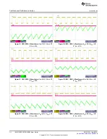
Figure 19. SW1, SW2, I

L

Waveforms: V

IN

= 18 V, V

OUT

= 12

V, I

OUT

= 0 A

Figure 20. SW1, SW2, I

L

Waveforms: V

IN

= 18 V, V

OUT

= 12

V, I

OUT

= 5 A

Figure 21. SW1, SW2, I

L

Waveforms: V

IN

= 24 V, V

OUT

= 12

V, I

OUT

= 0 A

Figure 22. SW1, SW2, I

L

Waveforms: V

IN

= 24 V, V

OUT

= 12

V, I

OUT

= 5 A

Figure 23. SW1, SW2, I

L

Waveforms: V

IN

= 42 V, V

OUT

= 12

V, I

OUT

= 0 A

Figure 24. SW1, SW2, I

L

Waveforms: V

IN

= 42 V, V

OUT

= 12

V, I

OUT

= 5 A

Содержание LM5175RHF QFN

Страница 1: ...LM5175RHF QFN EVM User s Guide Literature Number SNVU518 April 2016 ...

Страница 2: ... 3 4 Enable Voltage Input 5 3 3 5 SYNC Input 6 4 Test Setup and Procedure 6 4 1 Test Equipment 7 4 2 Recommended Test Setup 7 4 2 1 Input Connections 7 4 2 2 Output Connections 7 4 3 Test Procedure 8 4 3 1 Line Load Regulation and Efficiency 8 4 3 2 Control Loop Gain and Phase 8 5 Test Data and Performance Curves 8 5 1 Efficiency 8 5 2 Line and Load Regulation 11 5 3 Bode Plots 11 5 4 Operating Wa...

Страница 3: ...fications Parameter Value Input Voltage VIN 5 5V to 42V 45V transient Output Voltage VOUT 12V Maximum Output Current IOUT 6A Default Switching Frequency fsw 400 kHz Synchronizable Frequency Range Up to 600 kHz Efficiency IOUT 5A VIN 6V to 36V 95 1 to 98 4 Board Size 6 layers 50 mm x 43 mm 1 98 in x 1 7 in 1 1 Additional Features Smooth Buck Boost Operation Ultra high 98 peak power conversion effic...

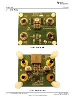
Страница 4: ... Photos www ti com 4 SNVU518 April 2016 Submit Documentation Feedback Copyright 2016 Texas Instruments Incorporated LM5175RHF QFN EVM User Guide 2 EVM Photos Figure 1 EVM Top Side Figure 2 EVM Bottom Side ...

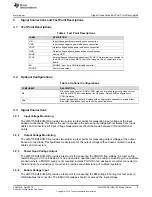
Страница 5: ...to enable dither See LM5175 datasheet on how to set the dither frequency 3 3 Signal Connections 3 3 1 Input Voltage Monitoring The LM5175RHFEVM HD provides two solder lug test points for measuring input voltage at the input banana connections This allows the user to measure the actual input voltage without losses from input cables and connectors All input voltage measurements should be made betwee...

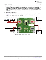
Страница 6: ...cy is set at 400 kHz by resistor RT1 However the converter aligns in frequency and phase with that of the applied SYNC signal up to 600 kHz If required apply an external SYNC signal with a frequency higher than the internal free running frequency as per the LM5175 device datasheet 4 Test Setup and Procedure Figure 3 shows the recommended test setup to evaluate the LM5175RHFEVM HD Working at an ESD...

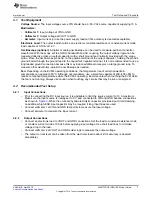
Страница 7: ... other waveforms adjust the oscilloscope as needed Fan Depending on the EVM s operating conditions the temperature rise of certain powertrain components can approach 50 C Although not mandatory use a small fan capable of 200 400 LFM to reduce component temperatures while the EVM is operating Exercise care when touching the EVM while the fan is not running Always use caution when touching any circu...

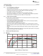
Страница 8: ...input source voltage to 0 V to power down 4 3 2 Control Loop Gain and Phase The resistor R16 on the LM5175RHFEVM HD is a convenient injection point for loop response analysis Set up EVM as described previously Connect isolation transformer secondary across R16 Connect output signal amplitude measurement probe TEST to VOUT and input signal amplitude measurement REF probe to opposite side of R16 Con...

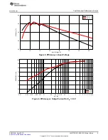
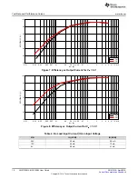
Страница 9: ...oltage V Efficiency 5 10 15 20 25 30 35 40 92 94 96 98 100 IOUT 3A IOUT 6A www ti com Test Data and Performance Curves 9 SNVU518 April 2016 Submit Documentation Feedback Copyright 2016 Texas Instruments Incorporated LM5175RHF QFN EVM User Guide Figure 5 Efficiency vs Input Voltage Figure 6 Efficiency vs Output Current for VIN 24 V ...

Страница 10: ...60 70 80 90 100 CCM DCM Test Data and Performance Curves www ti com 10 SNVU518 April 2016 Submit Documentation Feedback Copyright 2016 Texas Instruments Incorporated LM5175RHF QFN EVM User Guide Figure 7 Efficiency vs Output Current for VIN 6 V Figure 8 Efficiency vs Output Current for VIN 12 V Table 4 No Load Input Current IQ vs Input Voltage VIN IQ CCM IQ DCM 24V 35 mA 2 6 mA 12V 22 mA 12 mA 6V ...

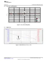
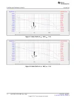
Страница 11: ... VIN 18V VIN 24V VIN 30V VIN 36V www ti com Test Data and Performance Curves 11 SNVU518 April 2016 Submit Documentation Feedback Copyright 2016 Texas Instruments Incorporated LM5175RHF QFN EVM User Guide 5 2 Line and Load Regulation Figure 9 Line and Load Regulation 5 3 Bode Plots Figure 10 Bode Plot for VIN 6V IOUT 3A ...

Страница 12: ...a and Performance Curves www ti com 12 SNVU518 April 2016 Submit Documentation Feedback Copyright 2016 Texas Instruments Incorporated LM5175RHF QFN EVM User Guide Figure 11 Bode Plot for VIN 12V IOUT 3A Figure 12 Bode Plot for VIN 24V IOUT 3A ...

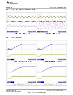
Страница 13: ...QFN EVM User Guide 5 4 Operating Waveforms 5 4 1 Switch Node Voltages and Inductor Current Figure 13 SW1 SW2 IL Waveforms VIN 6 V VOUT 12 V IOUT 0 A Figure 14 SW1 SW2 IL Waveforms VIN 6 V VOUT 12 V IOUT 5 A Figure 15 SW1 SW2 IL Waveforms VIN 12 V VOUT 12 V IOUT 0 A Figure 16 SW1 SW2 IL Waveforms VIN 12 V VOUT 12 V IOUT 5 A Figure 17 SW1 SW2 IL Waveforms VIN 16 V VOUT 12 V IOUT 0 A Figure 18 SW1 SW...

Страница 14: ...nts Incorporated LM5175RHF QFN EVM User Guide Figure 19 SW1 SW2 IL Waveforms VIN 18 V VOUT 12 V IOUT 0 A Figure 20 SW1 SW2 IL Waveforms VIN 18 V VOUT 12 V IOUT 5 A Figure 21 SW1 SW2 IL Waveforms VIN 24 V VOUT 12 V IOUT 0 A Figure 22 SW1 SW2 IL Waveforms VIN 24 V VOUT 12 V IOUT 5 A Figure 23 SW1 SW2 IL Waveforms VIN 42 V VOUT 12 V IOUT 0 A Figure 24 SW1 SW2 IL Waveforms VIN 42 V VOUT 12 V IOUT 5 A ...

Страница 15: ...tion Feedback Copyright 2016 Texas Instruments Incorporated LM5175RHF QFN EVM User Guide 5 4 2 Output Voltage Ripple 20 MHz Bandwidth Figure 25 VOUT Ripple IOUT 0A Figure 26 VOUT Ripple IOUT 5A 5 4 3 Startup Waveform Figure 27 Startup at VIN 8 V IOUT 0A Figure 28 Startup at VIN 8 V IOUT 4A Figure 29 Startup at VIN 12 V IOUT 0A Figure 30 Startup at VIN 12 V IOUT 4A ...

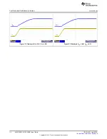
Страница 16: ... Performance Curves www ti com 16 SNVU518 April 2016 Submit Documentation Feedback Copyright 2016 Texas Instruments Incorporated LM5175RHF QFN EVM User Guide Figure 31 Startup at VIN 24 V IOUT 0A Figure 32 Startup at VIN 24 V IOUT 4A ...

Страница 17: ... 2 3 5 6 QL2 BSZ0902NS 100 R14 100 R13 100pF C11 100pF CT1 FOR SPREAD SPECTRU M MODULATION DITHER REPLACE Rcd WITH 0 047µF CAPACITOR 10µF Cin2 10µF Cin1 10µF Co6 GND 6 65k R15 TRIM SYNC 50 R16 LDRV1 SW1 LDRV2 SW1 LDRV1 HDRV1 HDRV1 HDRV2 SW2 HDRV2 SW2 LDRV2 10 0 R5 100pF C14 SYNC PGOOD D2 BAS516 115 D3 BAS516 115 EN GND GND GND GND GND EN UVLO 26 VIN 27 VINSNS 28 MODE 1 DITH 2 RT 3 SLOPE 4 SS 5 COM...

Страница 18: ...ments Incorporated LM5175RHF QFN EVM User Guide 6 2 PCB Layout Figure 34 through Figure 41 show the design of the LM5175 6 layer PCB with 2 oz copper thickness The EVM is a two sided design and it includes positions for input and output bulk capacitors Figure 34 Top Copper Top View Figure 35 Layer 2 Top View ...

Страница 19: ...ti com EVM Documentation 19 SNVU518 April 2016 Submit Documentation Feedback Copyright 2016 Texas Instruments Incorporated LM5175RHF QFN EVM User Guide Figure 36 Layer 3 Top View Figure 37 Layer 4 Top View ...

Страница 20: ...mentation www ti com 20 SNVU518 April 2016 Submit Documentation Feedback Copyright 2016 Texas Instruments Incorporated LM5175RHF QFN EVM User Guide Figure 38 Layer 5 Top View Figure 39 Bottom Copper Bottom View ...

Страница 21: ...entation 21 SNVU518 April 2016 Submit Documentation Feedback Copyright 2016 Texas Instruments Incorporated LM5175RHF QFN EVM User Guide Figure 40 Top Layer Silkscreen Top View Figure 41 Bottom Layer Silkscreen Bottom View ...

Страница 22: ...de Schottky 30V 200mA SOD 323 BAT54HT1G On Semi 2 D2 D3 Diode 100V 0 2A SOD 523 BAS516 NXP 1 L1 Inductor 3 3µH 7 7mΩ DCR 15A Irms 32A Isat PIMC135T 3R3MF Delta Inductor 3 3µH 3 4mΩ DCR 15A Irms 29A Isat 74439369033 Wurth 2 QH1 QL1 MOSFET N Channel 60V 40A PG TSDSON 8 BSZ042N06NS Infineon 2 QH2 QL2 MOSFET N Channel 30V 40A PG TSDSON 8 BSZ0902NS Infineon 2 R1 R8 Resistor Chip 200kΩ 1 10W 1 0603 Std ...

Страница 23: ...w ti com Revision History 23 SNVU518 April 2016 Submit Documentation Feedback Copyright 2016 Texas Instruments Incorporated Revision History Revision History DATE REVISION NOTES April 2016 Initial release ...

Страница 24: ...ring the warranty period to the address designated by TI and that are determined by TI not to conform to such warranty If TI elects to repair or replace such EVM TI shall have a reasonable time to repair such EVM or provide replacements Repaired EVMs shall be warranted for the remainder of the original warranty period Replaced EVMs shall be warranted for a new full ninety 90 day warranty period 3 ...

Страница 25: ... by Industry Canada to operate with the antenna types listed in the user guide with the maximum permissible gain and required antenna impedance for each antenna type indicated Antenna types not included in this list having a gain greater than the maximum gain indicated for that type are strictly prohibited for use with this device Concernant les EVMs avec antennes détachables Conformément à la rég...

Страница 26: ... connecting any load to the EVM output If there is uncertainty as to the load specification please contact a TI field representative During normal operation even with the inputs and outputs kept within the specified allowable ranges some circuit components may have elevated case temperatures These components include but are not limited to linear regulators switching transistors pass transistors cu...

Страница 27: ...F REMOVAL OR REINSTALLATION ANCILLARY COSTS TO THE PROCUREMENT OF SUBSTITUTE GOODS OR SERVICES RETESTING OUTSIDE COMPUTER TIME LABOR COSTS LOSS OF GOODWILL LOSS OF PROFITS LOSS OF SAVINGS LOSS OF USE LOSS OF DATA OR BUSINESS INTERRUPTION NO CLAIM SUIT OR ACTION SHALL BE BROUGHT AGAINST TI MORE THAN ONE YEAR AFTER THE RELATED CAUSE OF ACTION HAS OCCURRED 8 2 Specific Limitations IN NO EVENT SHALL T...

Страница 28: ...esponsible for compliance with all legal regulatory and safety related requirements concerning its products and any use of TI components in its applications notwithstanding any applications related information or support that may be provided by TI Buyer represents and agrees that it has all the necessary expertise to create and implement safeguards which anticipate dangerous consequences of failur...

Страница 29: ...Mouser Electronics Authorized Distributor Click to View Pricing Inventory Delivery Lifecycle Information Texas Instruments LM5175RHFEVM HD ...

Отзывы: