


swru138
22/33
7.3.3 USB
power
When SmartRF05EB is connected to a PC via a USB cable, it can draw power from the USB
bus. The onboard voltage regulator supplies approx 3.05 V to the board. The power source
selection jumper should short circuit pin 2 and 3 of header P11.
7.3.4 Laboratory power supply
When connecting a lab power supply, ground should be connected to any of the GND pads
on the board. Remove the power source selection jumper and apply a voltage in the range
from 2.7V to 3.6V to pin 2 on header P11. The main power switch will not have any effect in
this case.
WARNING!
Note that this will bypass all voltage regulators on the board so there might be a
risk of damaging the components on the board if the voltage on pin 2 on header P11 is lower
than -0.3V or higher than 3.9V (maximum ratings for CC2511).
7.4
UART RS232 interface
The UART interface can be used by custom applications for communication with other
devices. The interface uses a voltage translation device so that the port is compatible with
RS232 signalling. The RS232 voltage converter can be disabled by shorting pin 1 and 2 on
P10 with a jumper.
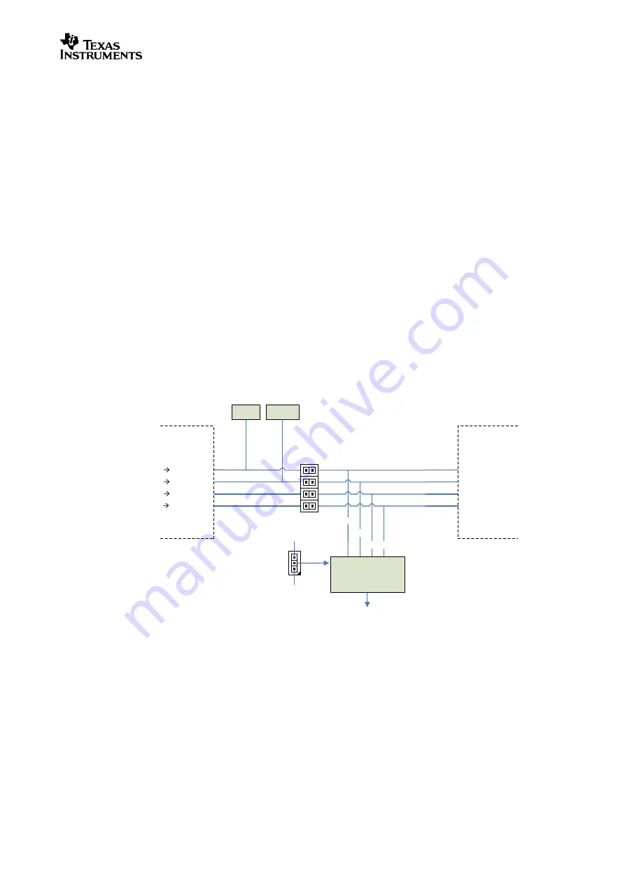
The figure below gives a detailed overview of the UART signals and how they are connected
to the different devices on the EB.
RTS
USB_UART_RTS CC2511 CTS
CTS
RX
TX
USB_UART_CTS CC2511 RTS
USB_UART_RX CC2511 TX
USB_UART_TX CC2511 RX
RTS
CTS
RX TX
LED
RS232
Level Converter
EN
EM Interface
CC2511
Button
P1
Vcc
GND
P10
P16
1-2
3-4
5-6
7-8
Figure 18 - UART RS232 signals and jumpers
As the figure shows, signals are crossed on the EB between the EM and CC2511 and
between the EM and the RS232 level converter/DE9 connector. The implication is that if the
board connected to the EM interface communicates with a PC using UART, use a straight
serial cable. To communicate with CC2511 from a PC, a null-modem cable (crossed) has to
be used. UART communication between CC2511 and the controller on the EM works without
crossing any signals (RX connected to TX and vice versa).
Also note that the USB button and USB LED share the RTS and CTS signals going to the
CC2511. To avoid any conflicts when the RTS/CTS UART flow control signal are used,
disconnect jumpers 1-2 and 3-4 on P1. They are disconnected by default.
Содержание CC2520
Страница 1: ...CC2520 Development Kit User s Guide swru138...
Страница 34: ...swru138 Appendix A SmartRF05EB Schematics...
Страница 35: ......
Страница 36: ......
Страница 37: ......
Страница 38: ......
Страница 39: ......
Страница 40: ......
Страница 41: ...swru138 Appendix B CCMSP EM430F2618 Schematics...
Страница 42: ......
Страница 43: ......
Страница 44: ......


