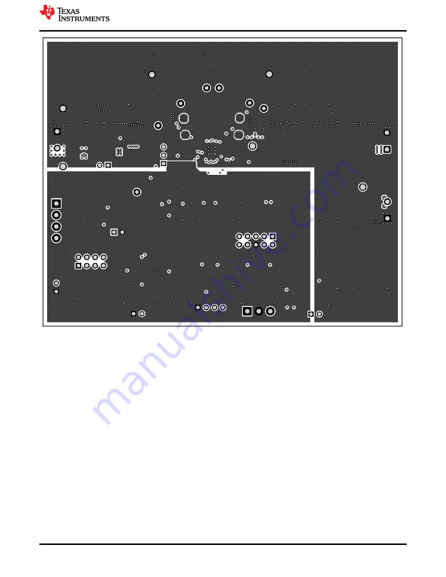
Figure 3-4. PCB Layer 2
www.ti.com
Bill of Materials, Board Layout, and Schematics
SLUUC74 – MAY 2021
Submit Document Feedback
BQ25720, BQ25723 Evaluation Module
15
Copyright © 2021 Texas Instruments Incorporated
Страница 1: ...2 Board Assembly Layout 12 3 3 Schematic 18 List of Figures Figure 2 2 Original Test Setup for BMS035 BQ2572x EVM 7 Figure 2 3 Main Window of the BQ2572x Evaluation Software 8 Figure 2 4 EN_OTG 9 Fig...
Страница 2: ...72x is a synchronous NVDC 1 battery buck boost charge controller offering a low component count high efficiency solution for space constrained multi chemistry battery charging applications The NVDC 1...
Страница 3: ...ription Factory Setting JP1 Bypass inrush control circuit spa JP1 on bypasses input FETs Q6 and Q7 external selector spa JP1 off CHRG_OK controls Q6 and Q7 external selector Installed JP2 Jumper on Fo...
Страница 4: ...5 5 9 15 20 26 V Battery voltage VBAT Voltage applied at VBAT terminal 0 19 2 V Supply current IAC Maximum input current from AC adapter input 0 6 4 A Output current Iout Output current 0 8 A Operati...
Страница 5: ...ues are not within specified limits the unit under test has failed Observe A B Observe if A B occurs If they do not occur the unit under test has failed Assembly drawings have locations for jumpers te...
Страница 6: ...5 Connect Load 2 in series with a current meter to J5 VBAT and PGND Connect a voltage meter across J5 VBAT and PGND Set 7 V at KEPCO load output Turn off load 2 Note Add a 47 F capacitor on the BAT p...
Страница 7: ...ect Charger and click the Next button b For SMBus BQ25720 select Charger_1_00_BQ25720 bqz on the Select a Target Page For I2C BQ25723 select Charger_1_00_BQ25723 bqz on the Select a Target Page c Afte...
Страница 8: ...ure 2 3 Main Window of the BQ2572x Evaluation Software Test Summary www ti com 8 BQ25720 BQ25723 Evaluation Module SLUUC74 MAY 2021 Submit Document Feedback Copyright 2021 Texas Instruments Incorporat...
Страница 9: ...4 V 0 5 V 5 Turn on LOAD 2 VBAT Load Measure V J5 VBAT 7 V 0 5 V Measure I J5 VBAT 2 A 0 5 V 2 4 2 OTG Function Use the following for OTG function settings 1 Connect a 7 V power supply to the VBAT loa...
Страница 10: ...323 SOD 323 BAT54HT1G ON Semiconductor D4 1 Green LED Green SMD 1 6x0 8x0 8mm LTST C190GKT Lite On H1 H2 H3 H4 4 Bumpon Hemisphere 0 44 X 0 20 Clear Transparent Bumpon SJ 5303 CLEAR 3M J1 J5 J6 3 Ter...
Страница 11: ...est Point Multipurpose Red TH Red Multipurpose Testpoint 5010 Keystone TP8 TP31 TP39 3 Test Point Multipurpose Black TH Black Multipurpose Testpoint 5011 Keystone U1 1 SMBus I2C 1 4 Cell Narrow VDC Bu...
Страница 12: ...illustrate the board assembly and layout images Figure 3 1 Top Assembly Bill of Materials Board Layout and Schematics www ti com 12 BQ25720 BQ25723 Evaluation Module SLUUC74 MAY 2021 Submit Document...
Страница 13: ...re 3 2 Bottom Assembly www ti com Bill of Materials Board Layout and Schematics SLUUC74 MAY 2021 Submit Document Feedback BQ25720 BQ25723 Evaluation Module 13 Copyright 2021 Texas Instruments Incorpor...
Страница 14: ...gure 3 3 PCB Layer 1 Bill of Materials Board Layout and Schematics www ti com 14 BQ25720 BQ25723 Evaluation Module SLUUC74 MAY 2021 Submit Document Feedback Copyright 2021 Texas Instruments Incorporat...
Страница 15: ...gure 3 4 PCB Layer 2 www ti com Bill of Materials Board Layout and Schematics SLUUC74 MAY 2021 Submit Document Feedback BQ25720 BQ25723 Evaluation Module 15 Copyright 2021 Texas Instruments Incorporat...
Страница 16: ...gure 3 5 PCB Layer 3 Bill of Materials Board Layout and Schematics www ti com 16 BQ25720 BQ25723 Evaluation Module SLUUC74 MAY 2021 Submit Document Feedback Copyright 2021 Texas Instruments Incorporat...
Страница 17: ...gure 3 6 PCB Layer 4 www ti com Bill of Materials Board Layout and Schematics SLUUC74 MAY 2021 Submit Document Feedback BQ25720 BQ25723 Evaluation Module 17 Copyright 2021 Texas Instruments Incorporat...
Страница 18: ...Z1 PGND 1 0 R13 VIN 4 3 2 Q9A DCX124EK 7 F 1 6 5 Q9B DCX124EK 7 F 10 0 R10 PGND 10 0k R17 3V3 7 8 1 2 3 5 6 Q7 4 7 8 1 2 3 5 6 Q6 470nF 50V C25 GND 1 2 3 4 J3 0022053041 10uF C26 300k R29 33pF C31 15...
Страница 19: ...ther than TI b the nonconformity resulted from User s design specifications or instructions for such EVMs or improper system design or c User has not paid on time Testing and other quality control tec...
Страница 20: ...These limits are designed to provide reasonable protection against harmful interference in a residential installation This equipment generates uses and can radiate radio frequency energy and if not in...
Страница 21: ...instructions set forth by Radio Law of Japan which includes but is not limited to the instructions below with respect to EVMs which for the avoidance of doubt are stated strictly for convenience and s...
Страница 22: ...any interfaces electronic and or mechanical between the EVM and any human body are designed with suitable isolation and means to safely limit accessible leakage currents to minimize the risk of electr...
Страница 23: ...R DAMAGES ARE CLAIMED THE EXISTENCE OF MORE THAN ONE CLAIM SHALL NOT ENLARGE OR EXTEND THIS LIMIT 9 Return Policy Except as otherwise provided TI does not offer any refunds returns or exchanges Furthe...
Страница 24: ...are subject to change without notice TI grants you permission to use these resources only for development of an application that uses the TI products described in the resource Other reproduction and...