Quick Start
5
SBAU316 – August 2018
Copyright © 2018, Texas Instruments Incorporated
BOOSTXL-ADS1219 BoosterPack™ User's Guide
When the desired firmware is selected, use the
Load Image
button to load the firmware into the
LaunchPad™.
Verify that the firmware installed successfully by checking the
Console
portion of the UniFlash tool at the
bottom of the GUI window.
2.3
Step 3
After the firmware file has successfully downloaded to the LaunchPad™, unplug the USB cable from the
LaunchPad™. Further communication takes place using the USB connector located at the opposite end of
the LaunchPad™. For proper power to be supplied to the BOOSTXL-ADS1219, remove the jumper from
the middle of the LaunchPad™ at JP6 and place the jumper on the center pins of JP1 (see
This jumper takes the available USB power from the bottom connector and applies the voltage to the
remainder of the board.
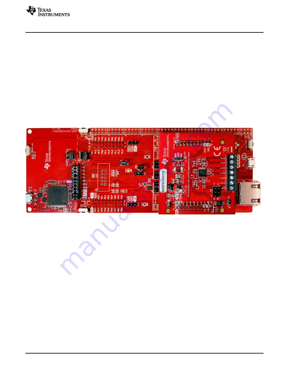
Before plugging the USB cable to the bottom LaunchPad™ USB connector, properly align the connectors
and attach the BOOSTXL-ADS1219 BoosterPack™ to the bottom set of connectors on the LaunchPad™
(
).
Figure 4. LaunchPad™ and BoosterPack™ Combo
When the BoosterPack™ is attached, plug the USB cable into the bottom connector of the LaunchPad™
and also to the PC. The LaunchPad™ communication to the PC is USB communications device class
(CDC) using a virtual COM port. Windows
®
10 automatically installs the required driver. Earlier versions of
the operating system may require a manual driver installation. The required driver files can be found in the
installation directory
Program Files (x86)/Texas Instruments/ADS1219/drivers
.
2.4
Step 4
From the Windows Start menu, go to the Texas Instruments folder and under ADS1219 start the GUI
application. The communication should automatically connect. If the hardware does not connect, manually
try to make the connection by clicking on the connect icon in the lower left portion of the GUI.


