Setup Details
12
SBAU316 – August 2018
Copyright © 2018, Texas Instruments Incorporated
BOOSTXL-ADS1219 BoosterPack™ User's Guide
4.2.2
LaunchPad™ Power Configuration
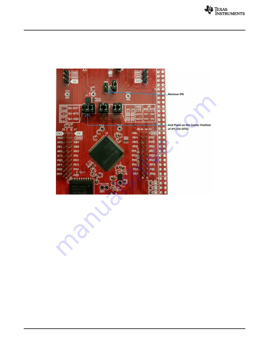
To reduce the number of cables required to communicate and power the BOOSTXL-ADS1219, the USB
connection at U7 can be used as the supply source for the LaunchPad™ as well as the communication
connection for the CDC virtual COM port to the GUI. To route the power correctly, use the jumper installed
on JP6 and connect to JP1 at the 5V-OTG (center) position as shown in
. There should now be
two jumpers on JP1.
Figure 12. Power Jumper Change
4.3
Driver Installation (If Required)
For Windows 10, the enumeration of a CDC device automatically installs the required driver on
enumeration. For earlier versions of the operating system a communication device class driver (CDC) may
need to be installed. If the driver shows as
unknown
, manually install the driver from
Program Files
(x86)/Texas Instruments/ADS1219/drivers
. Go to the
Control Panel
and select
Device Manager
. Right click
on the unknown device and select
Update driver
. Choose the selection
Browse my computer for driver
software
. Browse to the driver folder location and choose
Next
to locate the correct driver.
5
ADS1219 BoosterPack™ GUI Operation
illustrates the home page of the ADS1219 BoosterPack™ GUI. This page provides a high-level
overview of the ADS1219 device. Starting at the upper left portion of the GUI are various icons that refer
to particular pages within the GUI application. Along with the home page is the quick start, setup, chart,
register, and collateral pages. Each page can be selected by clicking on the appropriate icon. When the
MSP-EXP432E401Y LaunchPad™ is combined with the BOOSTXL-ADS1219 BoosterPack™ and
connected to the PC with the micro USB cable, the board is detected and connected. The connection
status is shown at the lower left corner of the GUI.


