


5 Installation
27
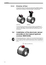
sensor assembly can only be inserted in its correct position in the
interchangeable fitting. The display of the electronic sensor assembly
points in direction from which the flow in the pipe comes.
•
Check the correct seating of the electronic sensor assembly. It must
engage in place in such a way that it cannot turn.
The electronic sensor assembly can only be screwed on in one position as a
result of the cylindrical pin. The position is defined by the pin which fits into
the notch. However, the pin only fits into the notch after several turns.
•
Fasten the electronic sensor assembly by tightening the union.
•
Latch both halves of the hood back between the electronic sensor
assembly and the interchangeable fitting in the roll pins.
The mechanical assembling of the electronic sensor assembly is thus
finished.
•
Bring the electronic sensor assembly into measurement position
(OPEN), as described in chapter 6.1.1.
5.6 Electrical
connection
The instrument may only be installed by a qualified electrician. Follow the
national and international regulations regarding the installation of electro-
technical systems. The voltage supply is to be laid out in accordance with
EN50178, SELV, PELV. To meet the "limited voltage" requirements accord-
ing to UL 508, the instrument must be supplied from a galvanically isolated
source and protected against short-circuits by means of an overcurrent de-
vice.
If you use the 5-wire connection cable with potential-free pulse output that is
available as an option (
See section 3.3.2), proceed according to
sec-
tion 5.6.2 when connecting the electronic sensor assembly.
If you directly connect the electronic sensor assembly or use a 4-wire con-
necting cable, proceed according to
section 5.6.1.
5.6.1
4-wire pin assignment
If you do
not
use the connecting cable available as an option for the electri-
cal isolation at OUT1(
See section 3.3.2), the following line assignment is
valid for the connecting cable or the connector pin assignment directly at the
electronic sensor assembly.
Pin no.
Wire colour
Assignment
1
Brown
+L (19 - 30 V DC)
2 White
OUT2
3
Blue
0 V DC (GND)
4 Black
OUT1
Содержание 0699 6446 Series
Страница 2: ...2...
Страница 7: ...1 Introduction 7 0699 6446 Standard 1 1 10 1 20 1 30 1 40 3 3 10 3 20 1 50 1 12 1 12 1 11...
Страница 41: ...Notes 41...
Страница 42: ...Notes 42...
Страница 43: ...Notes 43...


