background image

14

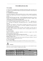
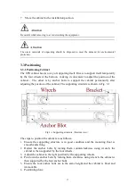
Attention

Auxiliary equipment is needed when the mounting floor is not solid enough to support the cabinet,
which helps distribute the weight over a larger area. For instance, cover the floor with iron plate or
increase the supporting area of the anchor bolts.

3.4 Battery

Three terminals

positive

neutral

negative

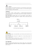
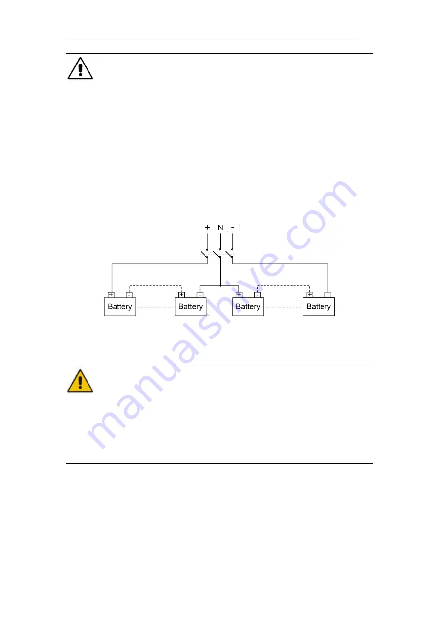
are drawn from the battery unit and

connected to UPS system. The neutral line is drawn from the middle of the batteries in

series (See Fig.3-2).

Select total number of batteries from 30 to 44 (even number), and the number of

positive and negative battery strings must be consistent. 10kVA could select the total

number 20pcs.

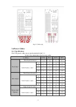
Fig 3-2 Battery string wiring diagram

Danger

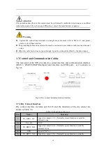
The battery terminal voltage is of more than 200Vdc, please follow the safety instructions to avoid
electric shock hazard.
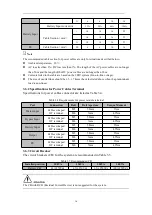
Positive and negative battery strings must be equipped with a 3-channel battery breaker with
limited current protection.
Ensure the positive, negative, neutral electrode is correctly connected from the battery unit
terminals to the breaker and from the breaker to the UPS system.

3.5 Cable Entry

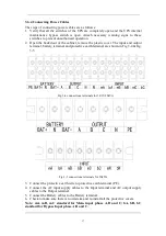
Cables can enter the UPS cabinet from the bottom. Cable entry is made possible

through a blanking plate fitted at the bottom of the equipment. The cable entry is

shown in Fig.3-3.

Содержание TEOS+ 300 Series

Страница 1: ...TEOS 300 SERIES 10 15 20 30 kVA 3 Phase In 3 Phase Out USER MANUAL...

Страница 2: ......

Страница 3: ...ce Engineer Note Our company is providing a full range of technical support and services Customer can contact our local office or customer service center for help The manual will update irregularly du...

Страница 4: ......

Страница 5: ...cture 8 2 4 1 UPS Configuration 8 2 4 2 UPS Outlook 8 3 Installation Instruction 11 3 1 Location 11 3 1 1 Installation Environment 11 3 1 2 Site Selection 11 3 1 3 Size and Weight 11 3 1 4 Installatio...

Страница 6: ...l Mode 41 5 2 3 Switching the UPS into Normal Mode from Bypass Mode 41 5 2 4 Switching the UPS into Maintenance Bypass Mode from Normal Mode 41 5 2 5 Switching the UPS into Normal Mode from Maintenanc...

Страница 7: ...s and remove conductive objects such as jewelry and watches to avoid electric shock or burns The operating environment has a certain impact on the service life and reliability of UPS The environmental...

Страница 8: ...ls use facial protection wear protective insulating clothing do not turn the battery upside down or tilt it disconnect the input breaker of the battery The installation environment of the battery must...

Страница 9: ...death or serious bodily injury if not avoided It is used to warn of potential dangerous situations which will lead to a certain degree of personal injury if not avoided It is used to transmit the safe...

Страница 10: ...gs should be installed to provide backup energy once the utility fails The UPS structure is shown in Fig 2 1 Fig 2 1 UPS Configuration 2 3 Operation Mode The UPS is an on line double conversion UPS th...

Страница 11: ...Mode If the inverter overload capacity is exceeded under Normal mode or if the inverter becomes unavailable for any reason the static transfer switch will perform a transfer of the load from the inver...

Страница 12: ...nance procedure See Fig 2 5 Fig 2 5 Maintenance mode operation diagram Danger During Maintenance mode dangerous voltages are present on the terminal of input output and neutral even with the LCD turne...

Страница 13: ...e after EOD The system starts after a delay time when the AC mains input recovers The mode and the delay time are programmed by the commissioning engineer 2 3 7 Frequency Converter Mode By setting the...

Страница 14: ...Standard Backup Type S Circuit Breakers 5 Standard Dual Input 1 Standard Parallel Card 1 Optional Dry Contact Card 1 Optional Long Backup Type H Circuit Breakers 4 Standard Dual Input 1 Standard Para...

Страница 15: ...9 Fig 2 9 10 15 kVA back appearance Long backup type Fig 2 10 10 20kVA back appearance Standard backup type...

Страница 16: ...d start button used to light up the LCD in battery mode 5 RS232 used to connect monitoring software 6 RS485 used to connect monitoring software 7 USB B type used to connect monitoring software 8 EPO 9...

Страница 17: ...nt must meet EN50272 2001 requirements If external batteries are to be used the battery circuit breakers or fuses must be mounted as close as possible to the batteries and the connecting cables should...

Страница 18: ...t Leveling Heat gun Heat heat shrinkable tubing Insulated monkey wrench Tighten and loosen bolts Electrician s knife Wire stripping Insulated torque wrench Tighten and loosen bolts Cable tie Bundle Cr...

Страница 19: ...nently after adjusting the position of the cabinet The supporting structure is shown in Fig 3 1 Fig 3 1 Supporting structure Bottom view The steps to position the cabinet are as follows 1 Ensure the s...

Страница 20: ...ositive and negative battery strings must be consistent 10kVA could select the total number 20pcs Fig 3 2 Battery string wiring diagram Danger The battery terminal voltage is of more than 200Vdc pleas...

Страница 21: ...10kVA 15kVA 20kVA 30kVA Main Input Main Input Current A 20A 29A 39A 58A Cable Section mm A 6 6 10 16 B 6 6 10 16 C 6 6 10 16 N 6 6 10 16 Main Output Main Output Current A 15A 23A 30A 45A Cable Section...

Страница 22: ...r 3 6 2 Specifications for Power Cables Terminal Specifications for power cables connector are listed as Table 3 4 Table 3 4 Requirements for power module terminal Port Connection Bolt Bolt Aperture T...

Страница 23: ...ttery terminal and protective earth terminal are shown in Fig 3 4 Fig 3 5 Fig 3 4 connections terminals for 10 15 20kVA Fig 3 5 connections terminals for 30kVA 3 Connect the protective earth wire to p...

Страница 24: ...er 3 7 Control and Communication Cables The rear panel of the UPS provides dry contact interface and communication interface RS232 RS485 SNMP Intelligent card interface and USB port as it is shown in...

Страница 25: ...Kohm B25 50 3275 please confirm with the manufacturer or contact the local maintenance engineers when placing an order The output dry contact interface An auxiliary dry contact signal will be activate...

Страница 26: ...phone Please refer to supporting operation instruction for details GPRS card allows UPS to connect the Internet through GPRS data local SIM card is required and the server for data communication and...

Страница 27: ...Control and display panel The LCD panel for cabinet is divided into two functional areas LED indicator LCD touch screen 4 2 1 LED Indicator There are 2 LEDs on the panel to indicate the operating sta...

Страница 28: ...The menu structure of the monitoring display interface is shown in Fig 4 2 Fig 4 2 Menu 4 2 3 Home page After the monitoring system starts self test the system enters the home page following the welc...

Страница 29: ...disabled Alarm status which becomes lit to indicate an alarm and off to indicate no alarm Password login logout key After clicking enter user password or advanced password by the keyboard The screen...

Страница 30: ...current Frequency Hz Mains input frequency PF Mains input Power factor Bypass The menu interface of the bypass input is shown in Fig 4 5 and the interface description is shown in Table 4 7 Fig 4 5 By...

Страница 31: ...V Battery voltage Battery Current A Battery current Battery status Current battery status idle discharge boost charge floating charge None Temperature Current operating temperature of battery optiona...

Страница 32: ...VA Output reactive power of each phase of the UPS unit PF Output power factor of each phase of the UPS unit Other The interface of other menu is shown in Fig 4 8 and the interface description is shown...

Страница 33: ...tus Last discharge Date of previous discharge status of UPS Batt expire time When the system time exceeds the warranty period the status bar will prompt the warranty information of battery UPS expire...

Страница 34: ...the type of alarm you want to view The interface of alarm menu is shown in Fig 4 11 Fig 4 11 Alarm menu interface Active alarm The active alarm interface displays the relevant information of the curre...

Страница 35: ...l information interface you can select relevant operation from the left secondary menu which contains On Off and Maintain On Off The interface of the On Off menu is shown in Fig 4 12 and the interface...

Страница 36: ...t be in normal condition the battery capacity should be above 25 Bat Test2 This test will lead to the battery being partly discharged to activate battery until battery voltage is low Bypass must be in...

Страница 37: ...he password which can be set to 1 8 digits Communication settings The interface of the communication setting menu is shown in Fig 4 15 and the interface description is shown in Table 4 18 Fig 4 15 Com...

Страница 38: ...ion status of generator Select IN_DRY1_NC EPO EPO Select IN_DRY1_NC BCB online BCB on line input normally open Select IN_DRY2 3_NO BCB status BCB contact status connect with the normally open signal o...

Страница 39: ...scription is shown in Table 4 20 Fig 4 17 Bypass parameters interface Table 4 20 Description of bypass parameters interface Setting item Default Options Description Batt Type VRLA Lithium VRL A Batter...

Страница 40: ...s normal working mode in general Parallel Number 1 1 4 Set according to the actual frame numbers of the UPS system installed by the user Dev ID 1 1 16 Set device parallel ID Output voltage adjust 0 5...

Страница 41: ...rameters interface Table 4 22 Description of battery parameters interface Setting item Default Options Description Battery number 40 settable et according to the total number of battery cells connecte...

Страница 42: ...Discharge 232 Bypass fail Bypass Fail 233 Fan fail Fan fail 245 UPS maintenance breaker close Maintenance CB is Closed 336 System board and inverter module CAN communication abnormal System board and...

Страница 43: ...ut voltage abnormal 466 Input over frequency Input frequency abnormal 467 Input under frequency Input frequency abnormal 468 Input phase sequence error Input phase sequence is reverse 469 Input phase...

Страница 44: ...arge primary protection The discharge primary protection of Lithium battery BMS system has been trigered 570 Lithium battery charge secondary protection The charge secondary protection of Lithium batt...

Страница 45: ...current imbalance 645 Capture failure Capture failure 646 Load strike Load strike 647 Adjacent UPS request switching to bypass Adjacent UPS request switching to bypass 648 Parallel operation wire abn...

Страница 46: ...er goes normal 7 The UPS is in Normal Mode Close the battery circuit breakers and the UPS starts charging the battery 8 The starting up done Note When the system starts the stored setting will be load...

Страница 47: ...h by selecting the icon of Off the system transfer to Normal Mode Note Normally the system will transfer to the Normal mode automatically This function is used when the frequency of the bypass is over...

Страница 48: ...turned off the terminals of input and output may be still energized If you need to maintain the power module wait for 10 minutes to let the DC bus capacitor fully discharge before removing the cover 5...

Страница 49: ...ers can stop the discharging by the Stop Bat Test icon With the icon of Bat Test 1 batteries will be discharged for about 30 seconds and then re transfer to normal mode Fig 5 2 Battery maintenance 5 4...

Страница 50: ...nstallation of Parallel Operation System 5 5 1 Parallel system diagram Up to four UPS could be paralleled with a diagram as shown in Fig 5 4 Fig 5 4 Parallel diagram The parallel board is located at t...

Страница 51: ...must be connected to the same bypass source 2 The bypass and the main input sources must be referenced to the same neutral potential 3 Any RCD Residual Current detecting device if installed must be of...

Страница 52: ...ings are finished follow the steps below for the operation of parallel system setup 1 Close the output and input breaker of the first unit Wait for the start up of bypass static switch and rectifier a...

Страница 53: ...s battery life can be prolonged The battery life is mainly determined by the following factors 1 Installation The battery should be placed in dry and cool place with good ventilation Avoid direct sunl...

Страница 54: ...the major contaminants controlled by government Therefore its storage transportation use and disposal must comply with the national or local regulations and laws about the disposal of hazardous waste...

Страница 55: ...t requirements of UPS EN50091 3 IEC62040 3 AS 62040 3 VFI SS 111 Note The above mentioned product standards incorporate relevant compliance clauses with generic IEC and EN standards for safety IEC EN...

Страница 56: ...g neutral with the bypass input Rated Frequency 50 60Hz Input Voltage Range 304 478Vac Line Line full load 228V 304Vac Line Line load decrease linearly according to the min phase voltage Input Frequen...

Страница 57: ...Equalized charge voltage 2 35V cell selectable from 2 30V cell 2 45V cell Floated current and constant voltage charge mode Temperature compensation 3 0 selectable 0 5 0 mV cl Charger Voltage precisio...

Страница 58: ...talled for 10kVA There are 40 batteries of 7 9AH to be installed for 15 20kVA There are 60 batteries of 9AH to be installed for 30kVA Fig 6 1 is the installation of battery of the 10kVA standard UPS 1...

Страница 59: ...f the 15 20kVA standard UPS 1 Dismantle the covers and crossbeams 2 Install battery and fix the crossbeams 3 Connect the battery cable according to 4 Recover the cover the series number Fig 6 2 Instal...

Страница 60: ...54 Fig 6 3 is the installation of battery of the 30kVA standard UPS 1 Dismantle the covers and crossbeams 2 Install battery and fix the crossbeams...

Страница 61: ...ies number 4 Recover the cover Fig 6 3 Installation of battery the 30kVA standard UPS Warning Make sure the polarity of the battery is correct according to the diagrams above Test and confirm the batt...

Страница 62: ......

Страница 63: ...AGKK14730 06 2022...

Отзывы: