background image

15

Changing the blade

DANGER:

 Do not use any blade larger than the stated capacity of the saw. It may 

come into contact with the blade guard and cause harm.
Do not use a blade too thick to allow the outer blade washer to engage with the 

À

ats on 

the spindle. This will prevent the blade screw from securing the blade on the spindle.
Do not use this saw to cut metal or masonry.

1. Disconnect the machine from the power supply
2. Disengage the saw arm by pushing down on the operating handle pull and twist the 
    release knob.
3. Raise the arm to its highest position.
4. Hold blade guard in the up position and press spindle lock, (Fig.15) (Rotate blade 
    carefully until blade locks) 
5. Use hex key to remove the blade bolt (Fig.8 & 16) by loosening in a clockwise 
    direction. Note: This bolt has a left hand thread
6. Remove outer blade washer and blade.
7. Clean and lightly oil outer and inner blade washers, do not remove inner blade 
    washer.
8. Replace blade ensuring the teeth are in the correct direction for rotation. The blade 
    has a direction indicator arrow printed on it, the teeth must always face down.
9. Fit outer blade washer.
10. Depress the spindle lock.
11. Replace and tighten the blade lock bolt using the hex key to secure tightly.

+ROGURWDWLQJORZHUEODGHJXDUGDQGEROWFRYHULQSRVLWLRQDQGUH¿WWKH¿[LQJ

      screws.
13. Attach blade guard retracting arm to the rotating blade guard.
14. Check guard operates freely.
15. Rotate blade carefully ensuring it does not foul the guard.
16. Reconnect to power supply
17. Switch saw on and off before it reaches maximum speed to check for free running. 

Maintenance 

WARNING:

 For your own safety, make sure switch is off and unplugged from the 

power source before doing any maintenance or adjustments. Replace the power cord 
immediately if it is cut, worn, or damaged in any way.

Accessories

CAUTION: 

Use only accessories or attachments recommended for use with your 

T

HUUDWHNWRROVSHFL¿HGLQWKLVPDQXDO

 The use of any other accessories or attachments 

might present a risk of injury to persons. Only use accessory or attachment for its 
stated purpose.

General Maintenance

1. Keep the air vents free from obstruction and clean regularly

Содержание TSMS300LJ

Страница 1: ...User Manual Please read and retain for future reference 305mm Sliding Miter Saw TSMS300LJ...

Страница 2: ...Exploded Assembly Diagram NOTICE Actual product may vary from pictures shown...

Страница 3: ...1 1 2 9 5 4 3 6 7 2 6 7 27 28 10 10 21 8 20 23 24 22 12 13 15 24 23 19 28 25 17 27 18 11 16 17 18 Fig A Fig B 14 4 26...

Страница 4: ...ping device 9 Top handle 10 Workpiece support 11 Stop rail 12 Table insert 13 Supporting foot 14 Locking screw 15 Pointer 16 Scale 17 Turntable 18 Fixed saw table 19 Scale 20 Pointer 21 Locking screw...

Страница 5: ...Fig 1 Fig 3 Fig 4 Fig 2 Fig 5 Fig 7 Fig 6 Fig 8...

Страница 6: ...Slide lock Fig 9 Fig 10 Fig 11 Fig 12 Fig 13 Fig 14 Fig 15 Fig 16...

Страница 7: ...Fig 17 Fig 18...

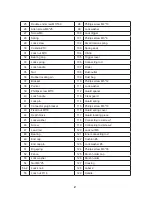
Страница 8: ...bber baffle 9 Battery 82 Label 1 10 Battery box 83 Depth adjusting screw 11 Laser 84 Allen screw M6 35 12 Laser seat 85 Hex nut M6 25 13 Phillips screw M4 8 86 Screw M6 14 Phillips screw M6 14 87 Bear...

Страница 9: ...Pointer 111 Lock washer 39 Phillips screw M5 8 112 Guard spacer 40 Lock handle 113 Clear guard 41 Lock pin 114 Guard spring 42 Connector plug bracket 115 Phillips screw M6 10 43 Fixed nut M5 8 116 Gu...

Страница 10: ...crew M8 16 137 Handle 64 Outer pressure plate 138 Carry handle 65 Blade 139 Phillips screw ST6 3 20 66 Locating ring for blade 140 Phillips screw STM6 28 67 Inner pressure plate 141 Phillips screw M5...

Страница 11: ...7KLV PDQXDO RU DQ DUWZRUN FRQWDLQHG KHUHLQ PXVW QRW EH UHSURGXFHG LQ DQ VKDSH RU IRUP ZLWKRXW the expUHVV written conVHnt of ACL roup Ltd DiagUDPV within thiV manual may not be drawn proportionally X...

Страница 12: ...fumes Keep children and bystanders away while operating a power tool Distractions can cause you to lose control Electrical safety Before use ensure that the power outlet you are using matches the plug...

Страница 13: ...tool to work harder than it is designed to do Never use your power tool with broken parts such as switches guide fences or leg stands ALWAYS keep your power tools away from children Keep cutting tools...

Страница 14: ...padlocks master switches or by removing starter keys 8 USE THE RIGHT TOOL Don t force a tool or attachment to do a job for which it was not designed 9 USE THE PROPER EXTENSION CORD Make sure your exte...

Страница 15: ...y repaired or replaced 23 Replace damaged blades cutters immediately DO NOT USE DAMAGED BLADES CUTTERS They may cause bodily injury 24 DIRECTION OF FEED Feed work into the blade cutter against the dir...

Страница 16: ...your hand to secure the work piece 5 Never reach around saw blade 6 Turn off tool and wait for saw blade to stop before moving work piece or changing settings 7 Unplug tool before changing blade or s...

Страница 17: ...ing 24 Stop operation immediately if you notice anything out of the ordinary 25 Do not attempt to lock the trigger in the on position 26 Stay alert Blades are extremely dangerous 27 Use only accessori...

Страница 18: ...ontrols or adjustments or performance of procedures other than those VSHFL HG KHUHLQ PD UHVXOW LQ KD DUGRXV ODVer light exposure DO NOT DISASSEMBLE LASER MODULE The laser is a CLASS II LASER PRODUCT t...

Страница 19: ...t sunlight relocate the work area to a place not exposed to the direct sunlight Using your miter saw Important Note Transporting or moving this machine must only be done with the arm in the locked pos...

Страница 20: ...Adjust the fence until square 9 Retighten the fence screws 10 Adjust the pointer to read 0 degrees Blade Cutting Depth Adjustment for use when trenching The blade is factory set to cut all the way thr...

Страница 21: ...ved to either side of the table by loosening the locking knob Ensure this knob is retightened before using the saw Support long lengths using roller support stands Slide Cutting 1 Pull and twist the r...

Страница 22: ...irection for rotation The blade has a direction indicator arrow printed on it the teeth must always face down 9 Fit outer blade washer 10 Depress the spindle lock 11 Replace and tighten the blade lock...

Страница 23: ...ce it Dull blades will cause increased tear out and ragged edges on the cuts 7 Lubricate all moving parts at regular intervals 8 To clean the body of the power tool only use a soft damp cloth Do NOT i...

Страница 24: ...hat it conforms to CE EMC LVD MD and RoHS directives EN55014 1 A1 2009 EN55014 2 A2 2008 EN61000 3 11 2000 EN61000 3 2 A2 2009 All provisions of Annex 1 of Council Directive 2004 108 EC EMC directive...

Страница 25: ...do any repairs or replace any parts of this product ACL Group Intl Ltd and its distributor expressly state that all repairs or parts replacement should be done by certified or licensed technicians The...

Отзывы: