


41
SERVICING
Installation and Servicing
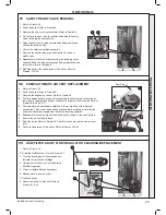
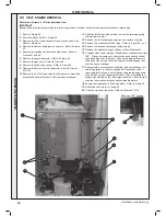
49 SPARK GENERATOR REPLACEMENT
1.
Refer to Frame 42.
2.
Disconnect the leads from the spark generator.
3.
Gently push down the generator to release the top clip
from the gas valve mounting bracket.
4.
Lift the spark generator up and out of the bottom retaining
moulding.
5.
Fit the new spark generator and re-assemble in reverse
order ensuring that the the earth lead is replaced.
6.
Check the operation of the boiler. Refer to Frames 31 & 32.
Spark Generator
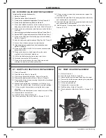
50 GAS CONTROL VALVE REPLACEMENT
1.
Refer to Frame 42.
2.
Unplug the electrical lead connection from the gas control valve.
3.
Remove the outlet gas valve clip and slide the pipe upwards.
4.
Undo the gas inlet pipe union at the inlet to the gas valve.
5.
Undo the single screw fixing the gas valve to the mounting
bracket and withdraw the valve forwards.
6.
Fit the new gas control valve ensuring that the ‘o’ ring and
sealing washer are in place and reconnect gas and electrical
connections.
7.
Check the operation of the boiler. Refer to Frames 31 & 32.
4
5
3
2
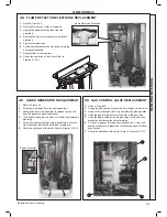
48 FLAME DETECTION ELECTRODE REPLACEMENT
12.5mm
Str
aig
ht
ed
ge
1.
Refer to Frame 42.
2.
Remove the burner. Refer to Frame 45.
3.
Unplug the flame detection lead from the
electrode.
4.
Remove the 2 screws retaining the detection
electrode.
5.
Remove the electrode.
6.
Fit the new flame detection electrode, using the
new gasket supplied.
7.
Reassemble in reverse order.
8.
Check the operation of the boiler. Refer to
Frames 31 & 32.
Flame Detection Electrode
SER
VICING
Содержание LOGIC Combi 31
Страница 2: ...2 Installation and Servicing ...
Страница 57: ...57 NOTES Installation and Servicing ...
Страница 58: ...58 NOTES Installation and Servicing ...
Страница 59: ...59 NOTES Installation and Servicing ...


