


Document 57.4400.7200 - 1
st
Edition 03/2005
INDEX
iii
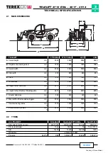
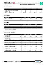
TELELIFT 3713 Elite - 4017 - 4514
INTRODUCTION
The hydraulic energy produced by the drive pump
(pos.
2)
is converted into mechanical power by a closed-loop
hydrostatic motor, model Bosch-Rexroth A6VM80
(pos.
5)
equipped with adjustment valve of DA1 type and with
flush valve for reducing the max temperatures inside
the drive circuit.
The motor is flanged to a two-speed mechanical
gearbox, model 357
(pos. 6)
manufactured by Dana.
Speeds are engaged by a special oil-dynamic cylinder
located inside the gearbox, while the selection of the
first and second speed is controlled by a 4-way/3-
position solenoid valve
(pos. 7)
of the on/off type.
The mechanical torque at the gearbox output is
transmitted to the front axle
(pos. 26)
and the rear axle
(pos. 25)
, both model 212 manufactured by Dana,
through Cardan shafts.
The hydraulic drive
(pos. 12)
of “load sensing” type with
a displacement of 315 cm
3
, receives oil from the priority
line of the pump
(pos. 3)
in relation to the “load sensing”
signal sent by the hydraulic drive and connected to such
pump with function of pilot signal. In this way, the input
flow to the hydraulic drive will be exactly the one needed
for the instantaneous steering functions; any excess flow
of the pump will be available for the functions of the
telescopic boom.
The steering circuit is protected against input
overpressures by a pressure reducing valve set at 140
bar. On the two delivery lines, there are other two
reducing valves with anti-shock function set at 200 bar.
The scope of these two valves is limiting possible shocks
on the steering wheel due to overstress on the steering
cylinders. The three pressure reducing valves are
installed in the hydraulic drive
(pos. 12)
and cannot be
regulated from the outside.
The steering circuit is completed by the front steering
cylinder
(pos. 14)
, the rear steering cylinder
(pos.
15)
[these cylinders being integral part of the front axle
(pos. 26)
and the rear axle
(pos. 25)
respectively] and
by a 4-way/3-position solenoid valve
(pos. 13)
for the
selection of the three different steer modes (rear wheels
straight, co-ordinate front/rear steering and independent
front/rear steering). When the solenoid valve
(pos. 13)
is not energised, the front steering cylinder is fed by the
hydraulic drive and the rear cylinder is blocked. When
one magnet or the other of the solenoid valve
(pos. 13)
is energised, the chambers of the cylinders are
connected in a different manner thus causing the desired
effect on the steering mode.
The Bucher/Tecnord electro-proportional distributor
(pos. 16)
, with 4 modular sections, receives oil from
the secondary line of the pump
(pos. 3)
and feeds all of
the movements of the telescopic boom.
Содержание TELELIFT 3713 Elite
Страница 4: ...Courtesy of Crane Market...


