


March 2022
Service Manual
Steer Axle Components
Part No. 1312899GT
GR
™
-20J • GR
™
-26J
71
Steer Axle Components
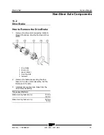
10-1 Y oke
10-1
Yoke Assembly
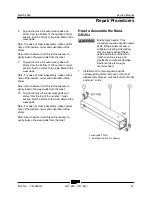
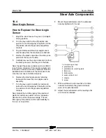
How to Remove the Yoke
Assembly
Note: Perform this procedure on a firm, level
surface with the machine in the stowed position.
1 Block the non-steer tires.
2 Loosen the bolts of the wheel at the steer end
of the machine. Do not remove the bolts.
3 Center a lifting jack under the drive chassis at
the steer end of the machine.
4 Raise the machine approximately 6 inches /
15 cm. Place blocks under the chassis for
support.
Crushing hazard. The chassis
will fall if not properly supported.
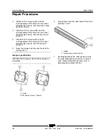
5 Lower the machine onto the blocks.
6 Remove the bolts from the wheel at the steer
end of the machine. Remove the wheel from
the machine.
7 Support and secure the yoke assembly to an
appropriate lifting device.
8 Remove the top cir-clip from the pin at the
steering rod.
9 Remove the plastic cap above the yoke pivot
shaft. Set the cap to the side.
10
Ground control side:
Remove the steer
sensor from the yoke pivot.
11 Remove the retaining fasteners from the yoke
pivot shaft and set aside.
12 Remove the yoke assembly from the
machine.
Bodily injury hazard. The yoke
assembly may fall if not
properly supported when it is
removed from the machine.
10-2 St eer Cylinde r
10-2
Steer Cylinder
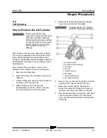
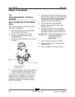
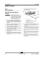
How to Remove the Steer
Cylinder
Note: When removing a hose assembly or fitting,
the O-ring (if equipped) on the fitting and/or hose
end must be replaced. All connections must be
torqued to specification during installation. Refer to
Specifications,
Hydraulic Hose and Fitting Torque
Specifications.
1 Turn the key switch to platform control and
pull out the red Emergency Stop button to the
on position at both the ground and platform
controls.
Note: Rotate the red Emergency Stop button at
platform control one quarter turn in a clockwise
direction to restore the power supply. The red
Emergency Stop button returns automatically to
the out, or on position.
2 Turn the wheels at the steer end of the
machine, 20° to 25° to the right.
3 Turn the key switch to the off position and
push in the red Emergency Stop button to the
off position at both the ground and platform
controls.
4 Block the non-steer tires.
5 Remove the pin retaining fasteners from the
top of the steer cylinder barrel-end pivot pin.
Содержание Genie GR-20J
Страница 12: ...Service Manual March 2022 xii GR 20J GR 26J Part No 1312899GT This page intentionally left blank ...
Страница 25: ...March 2022 Service Manual Part No 1312899GT GR 20J GR 26J 13 This page intentionally left blank ...
Страница 77: ...March 2022 Service Manual Function Manifold Part No 1312899GT GR 20J GR 26J 65 ...
Страница 113: ...March 2022 Service Manual 101 Electrica l Schemati cs Electrical Schematic GRJ from GRJL 2298 ...
Страница 116: ...Service Manual March 2022 104 Electrical Schematic GRJ from GRJL 2298 ...
Страница 117: ...March 2022 Service Manual 105 GCON LED Panel GRJ from GRJL 2298 ...
Страница 120: ...Service Manual March 2022 108 Temperature Sensor Harness GRJ from GRJL 2298 ...
Страница 121: ...March 2022 Service Manual 109 Options GRJ from GRJL 2298 ...
Страница 123: ...March 2022 Service Manual 111 Hydraulic Sc hema tics Hydraulic Schematic 2 2 kw from GRJL 2298 ...
Страница 127: ......


