


Service Manual
March 2022
Hydraulic Tank
68
GR
™
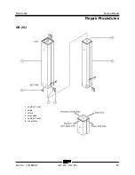
-20J • GR
™
-26J
Part No. 1312899GT
Hydraulic Ta nk
8-1 Hy dra ulic T ank
8-1
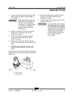
Hydraulic Tank
The primary functions of the hydraulic tank are to
cool and deaerate the hydraulic fluid during
operation.
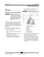
How to Remove the Hydraulic
Tank
Component damage hazard.
The work area and surfaces
where this procedure will be
performed must be clean and
free of debris that could get into
the hydraulic system.
Note: Perform this procedure on a firm, level
surface with the machine in the stowed position.
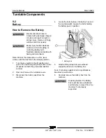
1 Disconnect the battery pack from the
machine.
2 Open and remove the turntable cover at the
hydraulic power unit side of the machine.
3 Working next to the hydraulic tank, remove
the fasteners securing the chassis side cover
to the chassis. Remove the side cover. Set
the side cover and fasteners to the side.
4 Tag and disconnect the wire harness
connectors from the function manifold.
5 Tag and disconnect the cables from the
motor.
6 Tag, disconnect and plug the hydraulic hoses
at the function manifold. Cap the fittings on
the manifold.
Bodily injury hazard. Spraying
hydraulic oil can penetrate and
burn skin. Loosen hydraulic
connections very slowly to allow
the oil pressure to dissipate
gradually. Do not allow oil to
squirt or spray.
7 Place a suitable container under the hydraulic
tank. Refer to Section 2, Specifications.
8 Locate and remove the hydraulic tank filler
cap. Set the filler cap to the side.
9 Remove the drain plug and drain all of the oil
into a suitable container.
10 Clean up any oil that may have spilled.
Properly discard the used oil.
11 Install the drain plug onto the hydraulic tank
and tighten to finger tight.
12 Install the filler cap onto the hydraulic tank
and tighten to finger tight.
13 Remove the clamp securing the hydraulic
power unit to the chassis. Set the clamp to the
side.
14 Carefully remove the hydraulic tank along with
hydraulic power unit from the machine and
place it on a clean work bench.
15 Remove the fasteners securing the function
manifold to the hydraulic tank. Set the
fasteners to the side.
16 Remove the clamp securing the hydraulic
power unit to the hydraulic tank. Set the
clamp to the side.
17 Remove the hydraulic power unit from the
hydraulic tank.
Torque specifications
Hydraulic oil reservoir drain plug
44 in-lbs
5 Nm
Manifold to tank fasteners
40 in-lbs
4.5 Nm
Содержание Genie GR-20J
Страница 12: ...Service Manual March 2022 xii GR 20J GR 26J Part No 1312899GT This page intentionally left blank ...
Страница 25: ...March 2022 Service Manual Part No 1312899GT GR 20J GR 26J 13 This page intentionally left blank ...
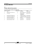
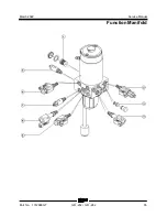
Страница 77: ...March 2022 Service Manual Function Manifold Part No 1312899GT GR 20J GR 26J 65 ...
Страница 113: ...March 2022 Service Manual 101 Electrica l Schemati cs Electrical Schematic GRJ from GRJL 2298 ...
Страница 116: ...Service Manual March 2022 104 Electrical Schematic GRJ from GRJL 2298 ...
Страница 117: ...March 2022 Service Manual 105 GCON LED Panel GRJ from GRJL 2298 ...
Страница 120: ...Service Manual March 2022 108 Temperature Sensor Harness GRJ from GRJL 2298 ...
Страница 121: ...March 2022 Service Manual 109 Options GRJ from GRJL 2298 ...
Страница 123: ...March 2022 Service Manual 111 Hydraulic Sc hema tics Hydraulic Schematic 2 2 kw from GRJL 2298 ...
Страница 127: ......


