Self-Balancing Robot
User Guide
11
www.terasic.com
July 12, 2018
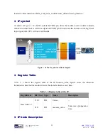
Figure 1- 9
is the symbol and the system block diagram of motor_measure.v. Here we only draw
the detecting diagram of the motor on the right, and the motor on the left also has the same module
to detect the speed.
The module phase_AB[1:0] is used to connect the motor to receive the waves from the Hall effect
sensor. The module can detect and obtain the motor speed and direction and save the data in the
module register. CPU can read the data from Avalon bus.
Figure 1- 9 The motor_measure.v module and the system block diagram(for the motor on the right)
⚫
⚫
R
R
e
e
g
g
i
i
s
s
t
t
e
e
r
r
T
T
a
a
b
b
l
l
e
e
Table 1- 3
is the IP register table. The
Counter
register in address “Base Addr+0” will counts the
motor pulse number. The system can detect how much the motor rotates according to this register,
and the positive number means clockwise direction, the negative number means counterclockwise
direction.
Counter
is read only register, the CPU can only read the Counter value. The
Counter
register in address “Base Addr+2” is for write. The
count_en
register in address “Base Addr+1” is
for controlling the two
Counter
s. When
count_en
is set to 1, the
Counter
register will start to count.
Table 1- 3 motor_measure.v IP Register
Reg Address
Bit Filed
Type
Name
Description
Base Addr + 0
31:16
RO
Unuse
-


