Self-Balancing Robot
User Guide
8
www.terasic.com
July 12, 2018
recounted.
PWM_OUT
represents one PWM cycle is finished. So, the longer the PWM cycle is, the
larger the
total_dur
value will be. In this demo, the
total_dur
register is set to 7000 as default, it is
one PWM cycle when the counter counts to 7000. The output PWM frequency is 7.14KHz
(50MHz/7000).
As shown in
Figure 1- 4
, the motor speed depends on
high_dur
register. During one PWM cycle,
when the
tick
value is less than
high_dur
, the PWM output is 1; otherwise, the PWM output is 0. So,
the PWM Duty Cycle depends on the
high_dur
. Therefore, the larger the
high_dur
value is, the
Duty Cycle will be larger and rotation speed will be faster.
Figure 1- 4 The diagram of relationship between total_dur and high_dur in PWM
1
1
.
.
2
2
D
D
e
e
t
t
e
e
c
c
t
t
t
t
h
h
e
e
M
M
o
o
t
t
o
o
r
r
s
s
p
p
e
e
e
e
d
d
a
a
n
n
d
d
D
D
i
i
r
r
e
e
c
c
t
t
i
i
o
o
n
n
Section 1.1
introduces how to control motor speed and direction, this section will introduce how to
use the Hall effect sensor and decoder on the motor to detect the motor speed and direction in real
time.
◼
◼
D
D
e
e
t
t
e
e
c
c
t
t
i
i
o
o
n
n
P
P
r
r
i
i
n
n
c
c
i
i
p
p
l
l
e
e
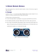
Figure 1- 5
shows the appearance of motor, there are two Hall effect sensors and one magnetic
Rotor on the motor. When the motor rotates, it will drive the magnetic Rotor to pass through the
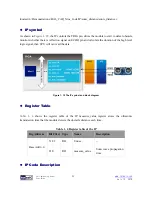
Hall effect sensors, and then, the Hall effect sensor magnetic force will change and generate Hall
effect voltage, a digital circuit will process the Hall effect voltage and output square wave pulse
(See
Figure 1- 6
).


