Self-Balancing Robot
User Guide
10
www.terasic.com
July 12, 2018
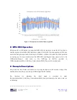
Figure 1- 7 Hall effect decoder output A B Phase waves
Figure 1- 8
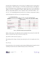
shows the motor phase pins connecting to FPGA. We can obtain the motor speed and
direction in real time by writing code to just detect the phase and pulse number of the two signals
(MTRR_IN_PA, MTRR_IN_PB).
Figure 1- 8 The motor phase pins connect to FPGA
◼
◼
E
E
x
x
a
a
m
m
p
p
l
l
e
e
D
D
e
e
s
s
c
c
r
r
i
i
p
p
t
t
i
i
o
o
n
n
We do provide a Qsys IP in the Self-Balancing Robot demo for users to obtain the motor speed and
direction, the IP can be found in folder:
\Demonstrations\BAL_CAR_Nios_Code\IP\motor_measure\motor_measure.v
⚫
⚫
I
I
P
P
S
S
y
y
m
m
b
b
o
o
l
l


