12
3. Loosen blower
−
wheel set screws from each motor shaft, ac-
cessing them through the blades of the blower wheels, with
a Phillips screwdriver. (See Fig. 16)
4. Disconnect one of the blower housings by removing the
four housing screws. (See Fig. 17)
5. Remove housing from support plate and motor shaft.
6. Pull motor out of second housing, which can remain at-
tached to the support plate.
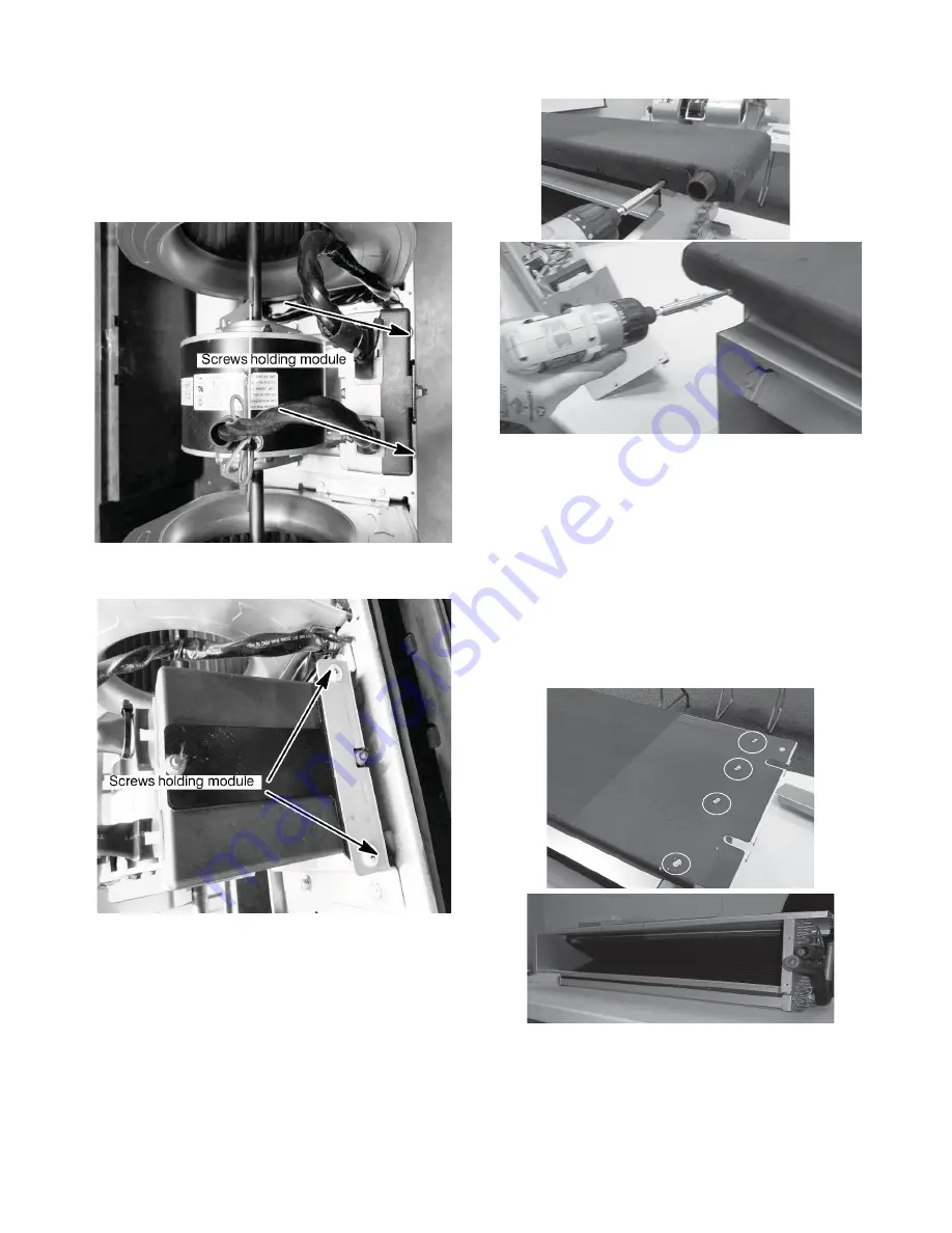
7. The ECM module is attached below the motor with two
Philips head screws to a bracket. (See Fig. 31 & 32)
A180048
Fig. 31
−
Remove Module
A180049
Fig. 32
−
Remove Module
8. Reverse these steps to reinstall.
H. Cleaning the A
−
Coil
The A
−
coil can be accessed for cleaning by removing either the
control box assembly or the blower assembly. (Refer to those
previous instructions.)
I. Removing the Drain Pan
1. Disconnect condensate drains, if necessary.
2. Remove the four screws located near the corners.
3. Lower drain pan from unit.
A13398
Fig. 33
−
Removing Condensate Pan
J. Changing the A
−
Coil
1. Disconnect power.
2. Disconnect field wiring (low and high voltage).
3. Disconnect condensate drain.
4. Remove entire fan coil unit from installation location.
5. Remove control box assembly. (See previous instructions.)
6. Remove blower assembly (See previous instructions.)
7. Remove drain pan (see previous) to the top plate.
8. From top of unit, remove the ten screws holding the coil
assembly to the top plate.
A13399
Fig. 34
−
Remove Top
−
Plate Screws
9. Remove the top plate and insulation.


