background image

Temperzone   SAT-­‐3   Installation   Setup   Guide,   Issue   2   


Page   4

   of   7   


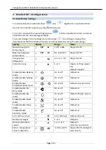
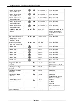
Zone   2   temperature   
sensor   calibration


i


OF


-­‐4.0   to   +4.0°C   

N/A   see   note   6   

Zone   3   temperature   
sensor   calibration   

i


OF


-­‐4.0   to   +4.0°C   

N/A   see   note   6   

Zone   4   temperature   

sensor   calibration   

i


OF


-­‐4.0   to   +4.0°C   

N/A   see   note   6   

Zone   5   temperature   
sensor   calibration   

i


OF


-­‐4.0   to   +4.0°C   

N/A   see   note   6   

Zone   6   temperature   
sensor   calibration   

i


OF


-­‐4.0   to   +4.0°C   

N/A   see   note   6   

Enable/disable   zone   
control   

i


ZONE   

En


On   or   off   

Default   off.   Must   be   off   
to   function   correctly   

without   zone   control   

board.   

Maximum   difference   of   
zone   setpoint   from   

zone   1   set   point   

i   

ZONE

    SP   

2.0   to   10.0°C   

N/A   see   note   6   

Minimum   number   of   
zones   that   must   be   on   

i   

ZONE

    nn   

0,   1   or   2   

N/A   see   note   6   

Zone   1   Size   

i


1   to   5   

N/A   see   note   6   

Zone   2   Size   

i   


0   to   5   

N/A   see   note   6   

Zone   3   Size   

i   


0   to   5   

N/A   see   note   6   

Zone   4   Size   

i   


0   to   5   

N/A   see   note   6   

Zone   5   Size   

i   


0   to   5   

N/A   see   note   6   

Zone   6   Size   

i   


0   to   5   

N/A   see   note   6   

Programmable   timer   
function   

i   


tF   

1   or   2   

Default   1   
(standard,   see   note   5)   

Set   display   backlight   
duration   

i   


bd   

0   to   59   s   

Default   30s   

Set   display   backlight   
intensity   

I   


bL   

0   to   10   

Default   10   

Set   modbus   device   
address   

i   


Ad   

1   to   99   

Default   8   
Other   settings   will   not   
function   correctly.   

Set   RS485   baud   rate   

i   


br   

1   to   4   

1:4800   
2:   9600   
3:14400   
Default      4:   19200   

Zone   controlled   auto   
mode   dead   band   

i   


Ab   

0   to   10.0°C   

N/A   see   note   6   


Содержание SAT-3

Страница 1: ...Temperzone SAT 3 Installation Setup Guide Issue 2 SAT 3 Installation Setup Guide Date 4 February 2016 Issue 2 Applies to SAT 3 room temperature controller part number 201 000 146 ...

Страница 2: ...Temperzone SAT 3 Installation Setup Guide Issue 2 ...

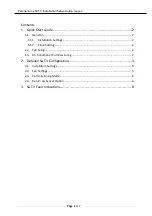
Страница 3: ...uide 2 1 1 General 2 1 1 1 Installation Settings 2 1 1 2 Clock Setting 2 1 2 Fan Setup 2 1 3 Air Conditioner Commissioning 2 2 Detailed SAT 3 Configuration 3 2 1 Installation Settings 3 2 2 Fan Settings 5 2 3 Commissioning Mode 6 2 4 Return Air Sensor Option 6 3 SAT 3 Fault Indications 8 ...

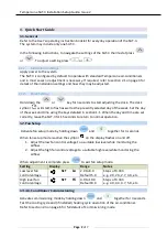
Страница 4: ...nd time using the keys detailed in section 1 1 When the day and time are set correctly leave the SAT 3 for 15 seconds to return to normal operation 1 2 Fan Setup Activate fan setup mode by holding down and together for 3 seconds When fan setup mode is active the symbol on the display flashes on and off 1 Adjust the low fan control voltage to a suitable low level while monitoring the airflow 2 Adju...

Страница 5: ...i SET Ht Ct to 50 0 C Steps of 0 5 C Temperature differential i td 0 5 to 1 5 C Steps of 0 5 C Indoor fan type i Ft 1 or 3 Single or three speed fan Default 3 speed Enable disable Heating mode i On or off Default on Enable disable Cooling mode i On or off Default on Enable disable Cool Heat auto mode i On or off Default on see note 1 Enable disable Fan Only mode i On or off Default on Enable disab...

Страница 6: ...point from zone 1 set point i ZONE SP 2 0 to 10 0 C N A see note 6 Minimum number of zones that must be on i ZONE nn 0 1 or 2 N A see note 6 Zone 1 Size i 1 to 5 N A see note 6 Zone 2 Size i 0 to 5 N A see note 6 Zone 3 Size i 0 to 5 N A see note 6 Zone 4 Size i 0 to 5 N A see note 6 Zone 5 Size i 0 to 5 N A see note 6 Zone 6 Size i 0 to 5 N A see note 6 Programmable timer function i tF 1 or 2 Def...

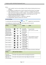
Страница 7: ...bol on the display flashes on and off Settings in Fan Setup Mode are as follows Setting Display Range Notes Low level fan control voltage SET Lo 2 0 to 8 0 Default 5 0 High level fan control voltage SET Hi 4 0 to 10 0 Default 8 0 Steps of 0 333 e g 2 0 2 3 2 7 3 0 etc Additional zone voltage increase SET Ad 0 to 950 Default 300 Zone 1 balance bL 10 to 100 Default 100 Zone 2 balance bL 10 to 100 De...

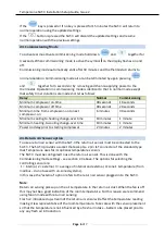
Страница 8: ...utes 1 minute Minimum heating to cooling change over time 10 minutes 1 minute Power on delay prior to starting compressor 2 minutes 2 minutes 2 4 Return Air Sensor option To use a return air sensor with the SAT 3 the return air sensor must be connected to the SAT 3 The SAT 3 provides a socket that accepts a 2 pin JST connector of the standard type that Temperzone uses for its optional temperature ...

Страница 9: ...ith the power disconnected Code displayed Description Remedy t1 SAT 3 internal temperature sensor error The internal temperature sensor of the SAT 3 is damaged Replace the SAT 3 t2 SAT 3 external temperature sensor error Check the external temperature sensor connected to the Sat 3 t3 No communications between SAT 3 and unit controller Check the wiring between the unit controller and the SAT 3 Chec...

Отзывы: