7
H
S
P1
ON
OFF
OUT1 Relay
A, B ,C = Re
s
et i
s
applied
O1.HY = Output1 hy
s
tere
s
i
s
PV
A
B
C
H
S
P1 – O1.HY
Figure 1.4
High Limit Operation
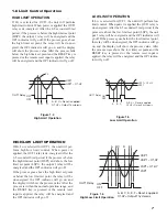
HIGH LIMIT OPERATION
If Hi. is selected for OUT1, the unit will perform
high limit control. When power is applied the OUT1
relay is de-energized. After the 6.5 second self-test
period, if the process is below the high limit set point
(HSP1) the output 1 relay will be energized and the
OP1 indicator will go off.If the process goes above
the high limit set point, the relay will be de-ener-
gized, the OP1 indicator will go on, and the display
will show the process value. After the process falls
below the high limit set point and the RESET key is
pressed or the remote reset input is applied, the relay
will be energized and the OP1 indicator will go off.
1–6 Limit Control Operation
LOW LIMIT OPERATION
If Lo. is selected for OUT1, the unit will perform low
limit control. When power is applied the OUT1 relay is
de-energized. After the 6.5 second self-test period, if the
process is above the low limit set point (LSP1) the out-
put 1 relay will be energized and the OP1 indicator will
go off.If the process goes below the low limit set point,
the relay will be de-energized, the OP1 indicator will go
on, and the display will show the process value. After
the process rises above the low limit set point and the
RESET key is pressed or the remote reset input is
applied, the relay will be energized and the OP1 indica-
tor will go off.
L
S
P1
ON
OFF
OUT1 Relay
A, B ,C = Re
s
et i
s
applied
O1.HY = Output1 hy
s
tere
s
i
s
A
B
C
L
S
P1 + O1.HY
Figure 1.5
Low Limit Operation
HIGH/LOW LIMIT OPERATION
If Hi.Lo is selected for OUT1, the unit will per-
form high/low limit control. When power is
applied, the OUT1 relay is de-energized. After the
6.5 second self-test period, if the process is below
the high limit set point (HSP1) and above the low
limit set point (LSP1), the output 1 relay will be
energized and the OP1 indicator will go off.
If the process goes above the high limit set point
or below the low limit set point, the relay will be
de-energized, the OP1 indicator will go on, and
the display will show the process value. After the
process is within the normal operation range, and
the RESET key is pressed or the remote reset
input is applied, the relay will be energized and
the OP1 indicator will go off.
L
S
P1 + O1.HY
H
S
P1
L
S
P1
H
S
P1 – O1.HY
ON
OFF
OUT1 Relay
A, B, C, D, E, F =Re
s
et i
s
applied
O1.HY= Output1 hy
s
tere
s
i
s
A
BC
D
E F
Figure 1.6
High/Low Limit Operation
Содержание TEC-410
Страница 26: ...24 ...


