


the waveforms displayed on the oscilloscope resemble those
in
.
-
switch off the ohmic load and switch off the main switch.
If one of the two signals is absent the control board should be
replaced (
Otherwise, if the machine does not supply AC
current the SCR module should be replaced, or if the worst comes
to the worst replace the secondary board.
Set switch SW2 to TIG/2T (toward to the top) and switch SW2 to
LIFT (in the centre). Connect the TIG torch and press the button to
verify that relay K1 closes
; if not check whether:
After checking operation for point 1.3 A), press the button and
check whether:
- the solenoid valve closes (fig. 2A); if not check whether:
- the voltage over the female fastons (
) is equal to 230Vac
±10%. If voltage is present this means the solenoid valve is
faulty, otherwise check the operation of relay K2 on the
secondary board;.
-
- the voltage over pin 1 (+) and pin 25 of J9 (control board) is
equal to +15Vdc ±20%, otherwise replace the control board.
Set switch SW2 to TIG/2T (as high as it will go) and switch SW3 to
AC (as low as it will go). Now reconnect only fastons J1 and J3 to
the HF generator board (
) and faston J1 on the support
board.
The high frequency voltage will permanently damage
any instrument connected to the generator.
With the TIG torch still connected and pressing the button check
whether:
-
the HF generator board starts to hum for about 2 seconds
(high frequency in torch); otherwise make sure the voltage
over female fastons J1 and J3 (
), disconnected from the
HF board, is equal to 230Vac ±10%; if voltage is present the
HF board is faulty; if not check the operation of transformer T1
and SCR Q1;
On the front panel set switch SW2 to MMA (as low as it will go),
switch SW3 to DC-LIFT (in the centre) and the welding current to
maximum. Under the load conditions shown in
, switch on the
machine and leave it in operation until the thermostatic capsules
trigger (machine in alarm). After making sure the internal wiring is
positioned correctly re-assemble the machine once and for all.
with the machine set up according to the instructions in the
handbook make a test weld with an electrode diam. 2.5 and the
current setting at 80A. Monitor the dynamic behaviour of the
power source, also checking for the presence of the Arc Force, by
first operating key SW1 and then the encoder.
with the machine set up according to the instructions in
the handbook make a test weld with a grey electrode diam. 2.4
and an argon gas bottle (gas flow at 4.5 litres/minute). Make a
weld on iron or steel with a current setting of 80A, monitor the start
and arc stability and make sure the piece melts properly. Also
check all the main properties of the machine that can be set from
the digital panel (see TAB.1).
with the machine set up according to the instructions in
the handbook make a test weld with a green electrode, diam.
1.6mm, and the argon gas bottle (gas flow at 10 litres/minute).
Make a weld on aluminium with a current setting of 40A and
Duty Cycle 80%, monitor the start and arc stability and make
sure the piece melts properly. Also check all the main properties
of the machine that can be set from the digital panel (see
TAB.1).
Fig. J
N.B.
fig. 3).
A) Checking torch button operation
(fig. 4)
B) Checking solenoid valve operation
fig.4
on the secondary board relay K2 closes (fig. 6); if not check
whether:
C)Checking HF generator operation
fig. 4
WARNING!
fig.4
D) Running time test and closing the machine
fig. I
E) Welding test
MMA:
TIG/DC:
TIG/AC:
1.3 Operational tests
- Operation of the torch button;
- Operation of diode bridge D2 on the torch button board;
- Operation of transformer T1 on the torch button board;
- 20-
TECHNOLOGY TIG 172 AC/DC
FIGURA E
6
3
2
1
4 5
1 1 0 0 0 0
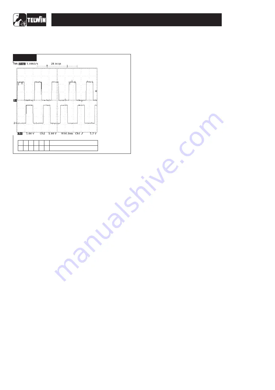
FIGURE J
SETTINGS
· THE FREQUENCY ON
CH1 AND CH2 IS
45KHz ±10%;
· AMPLITUDE ON CH1
AND CH2 IS 12V ±10%;
:
· PROBE CH1 x10;
· 5 V/Div;
· PROBE CH2 =10;
· 5V/Div;
· 10 sec/Div.
µ
VERIFY THAT
Number switch
Position switch
Содержание TECHNOLOGY TIG 172
Страница 7: ... 7 TECHNOLOGY TIG 172 AC DC WIRING DIAGRAMS General wiring diagram ...
Страница 8: ... 8 TECHNOLOGY TIG 172 AC DC Wiring diagram primary board Power Wiring diagram primary board Driver ...
Страница 10: ... 10 TECHNOLOGY TIG 172 AC DC Wiring diagram control board Digital Wiring diagram control board Analogyc ...
Страница 11: ... 11 TECHNOLOGY TIG 172 AC DC Wiring diagram control board In Out Wiring diagram secondary board Power ...


